Functions and Features

APPS

  • Emax
    Item no. 5100235

  • Peak load shaving for the maximum monitoring (Emax)

    • There are 64 steps of load shut down possible (depending on the hardware setup)
    • The configuration and monitoring is provided on the homepage of the device
    • The shutdown of each load can be activated by digital outputs of the FBM module (optional) via Profibus or Modbus
    • For the use of the APP you have to acquire the Emax license.
    • Device compatibility UMG 604 / UMG 605
  • Emax Sync
    Item no. 5100296

  • The APP stores synchronized Emax average power values in the device

    • The synchronizing pulse of the power supply utilities has to be connected to a free digital input of the measuring device
    • As a power source to calculate the average value impulses can be used as well as the direct measurement
    • The configuration can be set directly from the website
    • On the website of the device a spectral analysis of the measured values ​​is additionally shown
    • The Emax average values ​​can be read out with the GridVis and processed further
    • Spectral analysis reachs - depending on the set period of measurement period - to max. to the last Monday
    • An Emax release is not required
    • Device compatibility: UMG 604 / UMG 605 / UMG 509 / UMG 512
  • EN 50160 Watchdog
    Item no. 5100264 & 5100305

  • Integrated "Watchdog" function for continuous monitoring of the power quality per EN 50160

    The power quality on the supply side should comply with EN 50160. This standard describes various power quality parameters for the distribution of electrical power on public power grids. EN 50160 pertains to mains voltage, i.e. the voltage measured at the mains connection point. With power quality monitoring per EN 50160, all the algorithms (including for 95% and 100% values) are integrated in the measurement device itself.

    The auxiliary voltage of the device should be buffered to ensure that power failures can be reliably detected as events.

    • Integrated watchdog function
    • No need to transmit large volumes of measured data from the measurement device to a host system
    • Save on communications costs for applications with remote consumers
    • Simple analysis possible thanks to integrated colour display based on a "traffic light" system
    • Possible to perform power quality analyses even with no particular knowledge on the topic
    • No alarm functionality
    • Device compatibility: UMG 605 / UMG 512 (Item no. 5100264), UMG 605-PRO / UMG 512-PRO (Item no. 5100305)
    • APP EN 50160 Watchdog Power quality monitoring per EN 50160 with traffi c-light style indication and specifi c key variables for the power quality
  • FBM10 PT1000
    Item no. 5100211

  • Up to 10 additional thermistor inputs can be implemented via the RS485 interface by means of hardware expansion

    • Up to 10 additional thermistor inputs can be implemented via the RS485 interface
    • Hardware expansion FBM10 PT1000 – a DIN rail module with 10 PT1000 inputs – necessary for this
    • Device compatibility: UMG 604 / UMG 605 / UMG 508 / UMG 509 / UMG 511 / UMG 512 and PRO series
  • Humidity & Temperature JFTF-I
    Item no. 1506337

  • Processing and recording of up to 8 temperature / moisture sensors possible

    • Can process and record the measured values from up to 8 temperature/moisture sensors (item no. 1506074)
    • In doing so the display of the measured values is implemented via a homepage after installing the APP, or via global variables in the GridVis®
    • Measured values can be saved in a second Jasic® program via the graphical programming
    • Delivers two analogue 4 - 20 mA output signals, which will be processed by the function module FBM DI8AI8 (item no. 1506079)
    • Device compatibility: UMG 604 / UMG 605 / UMG 509 / UMG 512 and PRO series
  • GPS Sync
    Item no. 5100291

  • Sychronisation of the device time via digital input

    • A GPS receiver is required as an additional equipment (item number: 15.06.240)
    • Accuracy of synchronization with the device is +/- 1 second per GPS sync
    • This app is not required for the UMG 512 because the GPS receiver can be connected to the digital input 1 without an APP on the UMG512.
    • Device compatibility: UMG 604 / UMG 605 / UMG 509 and PRO series
  • IEC 61000-2-4 Watchdog
    Item no. 5100265 & 5100306 & 5100309 & 5100308

  • Integrated "Watchdog" function for continuous monitoring of the power quality per IEC 61000-2-4

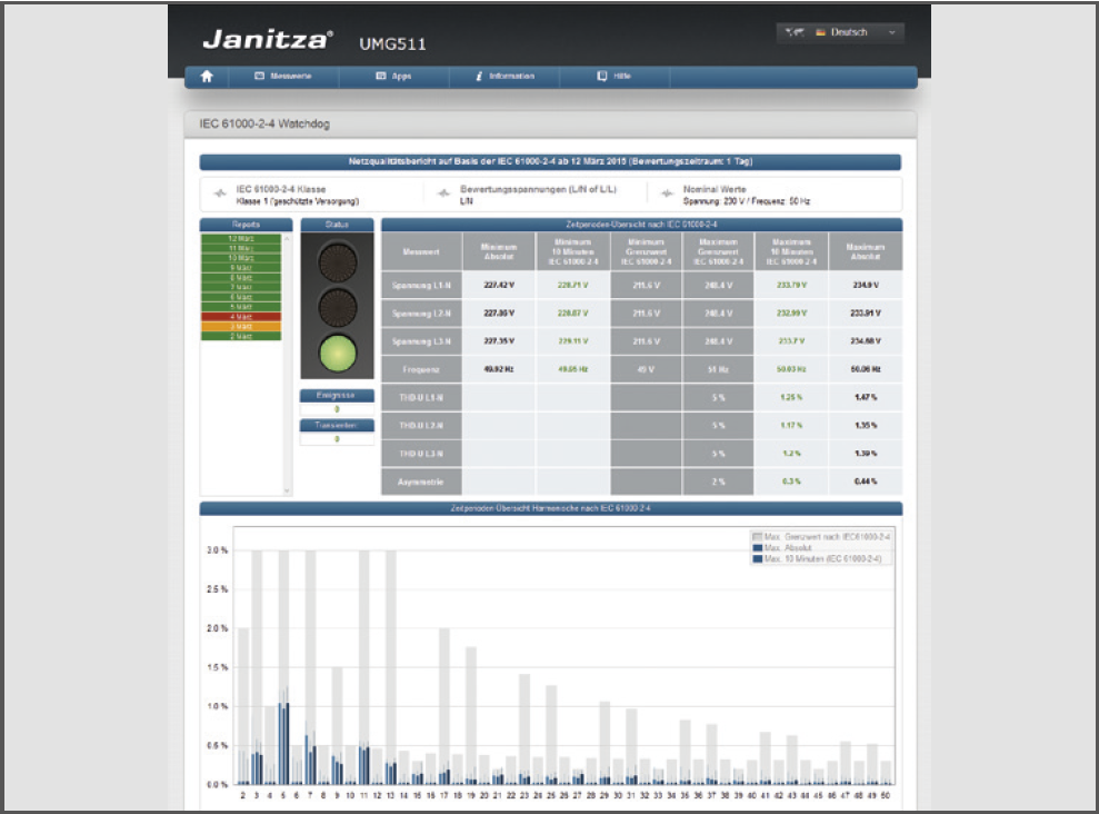
    The standard IEC 61000-2-4 defines numerical limits for industrial and private power distribution systems at rated voltages up to 35 kV. For the consumer, the standard IEC 61000-2-4 should be applied with reference to power quality. Therefore the power quality in all technical systems must be continuously monitored in accordance with IEC 61000-2-4, in order to ensure fault-free operation of the installed system.

    The auxiliary voltage of the device should be buffered to ensure that power failures can be reliably detected as events.

    • Integrated watchdog function in accordance with standard IEC 61000-2-4
    • No need to transmit large volumes of measured data from the measurement device to a host system
    • Save on communications costs for applications with remote consumers
    • Simple analysis possible thanks to integrated colour display based on a "traffi c light" system
    • Possible to perform power quality analyses even with no particular knowledge on the topic
    • No alarm functionality
    • Device compatibility: UMG 605 / UMG 512 (Item no. 5100265), UMG 605-PRO / UMG 512-PRO (Item no. 5100306), UMG 604 / UMG 509 (Item no. 5100309), UMG 604-PRO / UMG 509-PRO (Item no. 5100308)
    • APP IEC 61000-2-4 Watchdog Power quality monitoring per IEC 61000-2-4 with traffi c-light style indication and display of specifi c key variables for the power quality
  • Mini EnMs
    Item no. 5100266

  • Display of current and historical measured values in numbers and diagrams from one master device and max. 16 UMGs without memory, on the device's own homepage

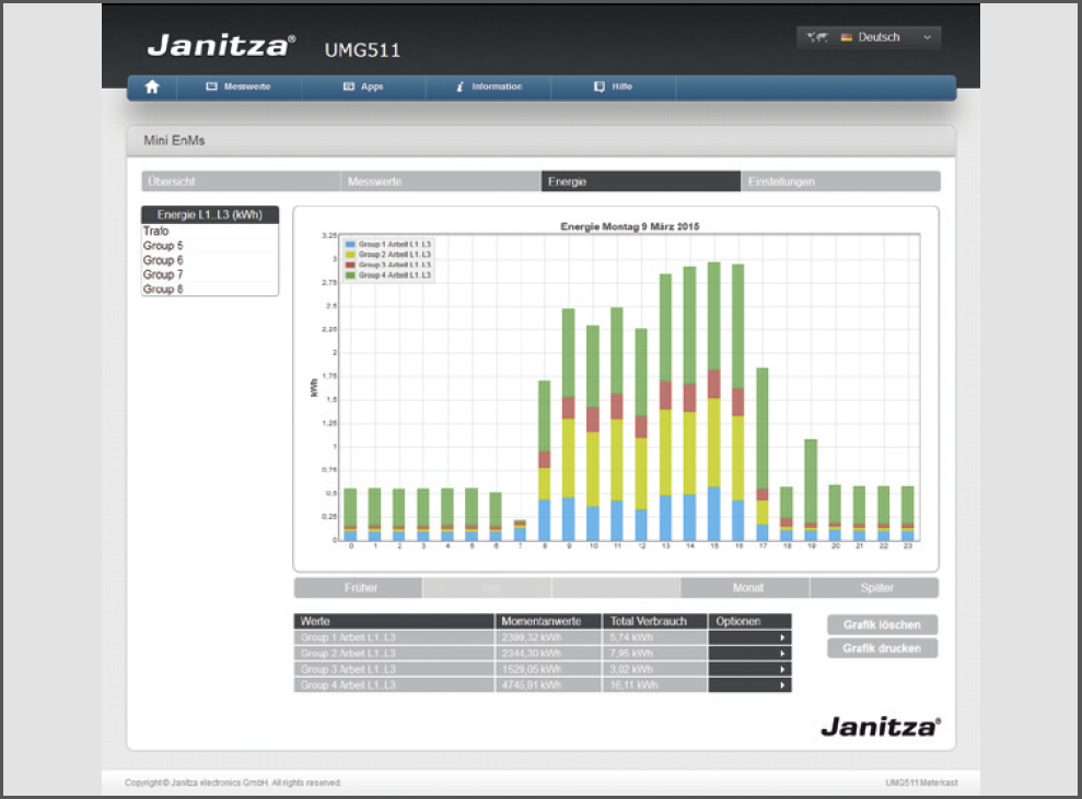
    With the "Mini EnMs" APP you can set up a small, local, web-based energy management system for a maximum of 16 Janitza devices without memory. Online and historical data from the master and slave devices are displayed via the web-based user interface. The master device also acts as a data collector for the slave devices.

    • Optimised for use on desktops, laptops or tablets
    • Select measured variables for the master device and slave devices using drag and drop
    • Select the desired time window with the integrated calendar function
    • The main variables of the Modbus slave are stored and displayed on the "main measurement device"
    • No external server or software package needed; just a standard browser will suffi ce
    • Maximum of 16 slaves (UMG 103, UMG 104 or UMG 96RM)
    • Memory variable for slave devices
      • Current L1, L2, L3
      • Total effective power
      • Total apparent power
      • Total effective energy
    • The master collects the data and presents it on its own device homepage.
      The APP was developed for small applications where GridVis® is not being used.
    • Device compatibility: UMG 604 / UMG 605 / UMG 509 / UMG 512 and PRO series
    • APP Mini EnMS Mini energy management system for display of selected measured variables
  • Multitouch
    Item no. 5100207

  • Reading out 30 measured values and max. 31 slave devices via RS485

    • Reads out 30 measured values (fi xed default value) from up to 31 slave devices (confi gurable) via RS485
    • Filing of the measured values in the master in global variables or on BACnet data points
    • Display of the measured values is implemented via the JPC35 touch panel or via the device homepage (browser with FLASH plug-in necessary)
    • Expansion for live value display
    • Integrated BACnet gateway function (option, item no. 52.16.083)
    • The BACnet-ID can be changed via the homepage
    • Program installs a control program
    • Depending on master device (UMG 604, UMG 605, UMG 508, UMG 511), call-up of a corresponding sub-program (slave devices: UMG 103, UMG 104, UMG 604, UMG 605 and UMG 96RM)
    • Possible communications fault (RS485-Bus) directly visible via a status display
    • The number of devices and device descriptions can be confi gured via the master devices homepage
    • The master device is automatically recognised and entered in the "Device type" fi eld
    • The BACnet confi guration is likewise implemented via the master device homepage
    • Each device can be assigned its own BACnet-ID
    • EDE fi le for the import of the BACnet data points in a BACnet-GLT is included in the scope of deliverables for the APP
    • Device compatibility: UMG 604 / UMG 605 / UMG 509 / UMG 512 and PRO series
    • APP Multitouch Overview of the measured values of each slave device
  • Push Service
    Item no. 5100238 & 5100307

  • Sending data directly from the measurement device to the energy portal

    • Sending data directly from the device to the energy portal (without additional software)
    • The delivery of data is implemented via port 80
    • Data can be visualised via a web server by means of a web browser
    • An APP must be installed on each device
    • Only Jasic®-capable devices are supported (UMG 604 / UMG 605 / UMG 508 / UMG 509 / UMG 511 / UMG 512)
    • UMG 96 RM-EL with integrated Push App function is supported
    • Prodata and UMG 20CM – only via Jasic®-capable devices
    • Sending of up to 25 measured values is possible simultaneously
    • Delivery of the last mean values from the ring buffer
    • APP automatically detects which data in the ring buffer is saved with which averaging time, and presents these for selection
    • The measured values to be sent can be selected via the homepage
    • Mean values are automatically synchronised to the device time
    • The transmission time can be adjusted for the transmission buffer. In the event of the network connection failing, there are no gaps in the data so long as the failure is shorter than the transmission buffer time
    • View of a status display on the homepage with the last data transmitted
    • Device compatibility:UMG 604 / UMG 605 / UMG 509 / UMG 512 (Item no. 5100238), UMG 604-PRO / UMG 605-PRO / UMG 509-PRO / UMG 512-PRO (Item no. 5100307)
    • Push service APP Status of the measured data transmission: listing of the last values sent
  • SNMP
    Item no. 5100310

  • The "Limit value alarm via SNMP" application monitors the settings made on the web page and in GridVis and sends an SNMP trap when it is exceeded

    • The trap number is freely selectable
    • Each trap number can be assigned to one or more monitor systems
    • This trap is then sent depending on the set logic (AND/OR), if only one limit value is exceeded (OR),
      or only when all configured limits of this trap have been exceeded (AND)
    • The traps can be sent up to two SNMP hosts
    • The following measured values ​​and events can be monitored:
      - Configuration via GridVis: voltage failure, undervoltage, overvoltage, overcurrent, transients, RCM (only UMG 509 & UMG 512)
      - Configuration via the web page: Frequency, Power, Heartbeat (watchdog, no configuration option).
    • Device compatibility: UMG 604 / UMG 605 / UMG 509 / UMG 512 and PRO series
  • Alert Messenger
    Item no. 5100209

  • Configurable Jasic® program for sending fault messages by email

    • Depending on confi guration, sending of fault messages with the following events: Total harmonic distortion voltage exceeded, short-term interruption detected, transient detected
    • Saving the meter readings for the event and transient messages in the Modbus register
    • Option to monitor additional measured values via an interface (not included)
    • Emails* with consumption values for day, week and month can be sent (a non-encrypted mail server is required)

      * The UMG range does not support SSL or TSL encryption.
    • Device compatibility: UMG 604 / UMG 605 / UMG 509 / UMG 512 and PRO series
    • APP fault message Energy report with daily trigger
  • RCM analysis
    Item no. 5100312

    • APP with extensive options for setting limit values and analysing fault currents in detail
    • Up to 20 RCM channels can be managed and evaluated via a gateway
    • The evaluation covers all types of residual current with an associated frequency analysis
    • For example, 50 Hz, pure DC or high-frequency residual currents in the 20 kHz range can be displayed individually
    • In addition, the application enables the proven dynamic limit value formation with Janitza energy measuring devices
    • Energy measuring devices can be assigned to each of the 20 RCM channels and limit values can be calculated as a function of power
    • APP RCM Analyse