Phase shifting and reactive power

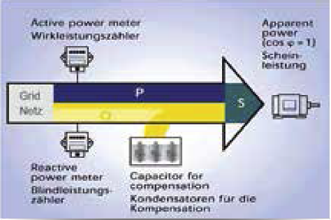
  • Reactive power is required in order to generate electromagnetic fields in machines such as three phase motors, transformers, welding systems, etc. Because these fields build up and break down continuously, the reactive power swings between generator and load. In contrast to the effective power it cannot be used, i.e. converted into another form of energy, and burdens the supply network and the generator systems (generators and transformers). Furthermore, all energy distribution systems for the provision of the reactive current must exhibit larger dimensions.

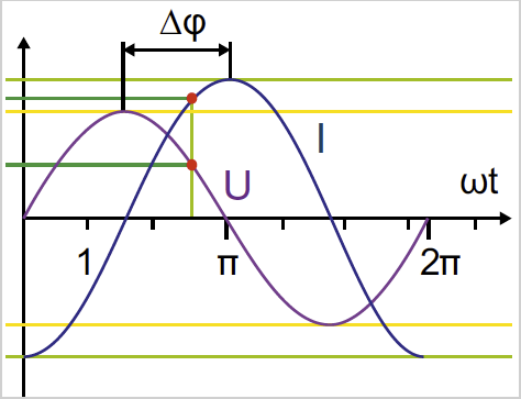
  • Fig.: Phase shifting between current and voltage (∆φ)
  • It is therefore expedient to reduce the inductive reactive power arising close to the load through a counteractive capacitive reactive power, of the same size where possible. This process is referred to as power factor correction. With power factor correction, the proportion of inductive reactive power in the network reduces by the reactive power of the power capacitor of the power factor correction system (PFC).The generator systems and energy distribution equipment are thereby relieved of the reactive current. The phase shifting between current and voltage is reduced or, in an ideal situation with a power factor of 1, entirely eliminated.

  • Fig.: Principle of power factor correction
  • The power factor is a parameter that can be influenced by mains interference such as distortion or unbalance. It deteriorates with progressive phase shifting between current and voltage and with increasing distortion of the current curve. It is defined as a quotient of the sum of the effective power and apparent power, and is therefore a measure of the efficiency with which a load utilises the electrical energy. A higher power factor therefore constitutes better use of the electrical energy and ultimately also a higher degree of efficiency.

  • Fig.: Power Factor (arithmetic)
  • Power Factor (arithmetic)

    • The power factor is unsigned
  • Abb.: Cosphi – Fundamental Power Factor

Cosphi – Fundamental Power Factor

  • Only the fundamental oscillation is used in order to calculate the cosphi
  • Cosphi sign (φ):
    - = for delivery of effective power
    + = for consumption of active power

Because no uniform phase shifting angle can be cited with harmonic loading, the power factor λ and the frequently used effective factor cos (φ1) must not be equated with each other. Starting with the formula (Grafik 1)

with I1 = fundamental oscillation effective value of the current, I = total effective value of the current, g1 = fundamental oscillation content of the current and cos(φ1) = shifting factor, one sees that only with sinusoidal form voltage and current (g = 1) is the power factor λ the same as the shifting factor cos(φ1). As such, exclusively with sinusoidal form currents and voltages is the power factor λ the same as the cosine of the phase shifting angle φ and is defined as (Grafik 2)

  • Grafik 1

  • Grafik 2