Selecting current transformers

Transformation ratio

The transformation ratio is the relationship between the primary rated current and the secondary rated current, and is cited on the rating plate as an unsimplified fraction.

Most frequently, x / 5 A current transformers are used. The majority of measuring devices have the highest precision class at 5 A. For technical and moreover economic reasons, x / 1 A current transformers are recommended with long measuring cable lengths. The line losses with 1-A transformers is only 4 % in comparison to 5-A transformers. However, the measuring devices here frequently exhibit a lower accuracy of measurement.

Rated current

Rated or nominal current (earlier designation) is the value of the primary and secondary current cited on the rating plate (primary rated current, secondary rated current), for which the current transformer is dimensioned. Standardised rated currents are (apart from in the classes 0.2 S and 0.5 S) 10 – 12.5 – 15 – 20 – 25 – 30 – 40 – 50 – 60 – 75 A, as well as the decimal multiples and fractions thereof. Standardised secondary currents are 1 and 5 A, preferably 5 A.

Standardised rated currents for the classes 0.2 S and 0.5 S are 25 – 50 – 100 A and their decimal multiples, as well as secondary (only) 5 A.

Correct selection of the primary nominal current is important for the accuracy of measurement. Recommended is a ratio slightly beyond the measured / defined maximum load current (In).

Example: In = 1,154 A; selected transformer ratio = 1,250/5.

The nominal current can also be defined on the basis of the following considerations:

  • Dependent on the mains supply transformer nominal current times approx. 1.1 (next transformer size)
  • Protection (rated fuse current = CT primary current) of the measured system part (LVDSB, subdistribution boards)
  • Actual nominal current times 1.2 (if the actual current lies considerably below the transformer or fuse nominal current then this approach should be selected)

Over-dimensioning the current transformer must be avoided, otherwise the accuracy of measurement significantly decrease especially with small load currents.

  • Rated power

    The rated power of the current transformer is the product of the rated load and the square of the secondary rated current and is quoted in VA. Standardised values are 2.5 – 5 – 10 – 15 – 30 VA. It is also permissible to select values over 30 VA according to the application case.The rated power describes the capacity of a current transformer to "drive" the secondary current within the error limits through a load.

    When selecting the appropriate power it is necessary to take into consideration the following parameters: Measuring device power consumption (with connection in series), line length, line cross-section.The longer the line length and the smaller the line cross-section, the higher the losses through the supply, i.e. the nominal power of the CT must be selected such that this is sufficiently high.

    The power consumption should lie close to the transformer's rated power. If the power consumption is very low (underloading) then the overcurrent factor will increase and the measuring devices will be insufficiently protected in the event of a short circuit under certain circumstances. If the power consumption is too high (overloading) then this has a negative influence on the accuracy.

    Current transformers are frequently already integrated in an installation and can be used in the event of retrofitting with a measuring device. It is necessary to note the nominal power of the transformer in this case: Is this sufficient to drive the additional measuring devices?

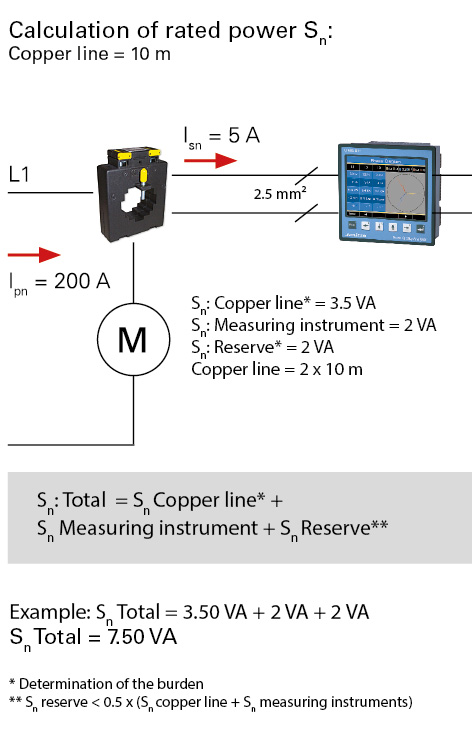
  • Fig.: Calculation of the rated power Sn (Copper line 10 m)

Precision classes

Current transformers are divided up into classes according to their precision. Standard precision classes are 0.1; 0.2; 0.5; 1; 3; 5; 0.1 S; 0.2 S; 0.5 S.The class sign equates to an error curve pertaining to current and angle errors.

The precision classes of current transformers are related to the measured value. If current transformers are operated with low current in relation to the nominal current then the accuracy of measurement declines.The following table shows the threshold error values with consideration to the nominal current values:

We always recommend current transformers with the same precision class for the UMG measuring devices. Current1 transformers with a lower precision class lead in the complete system – current transformer + measuring device – to a lower accuracy of measur3ement, which is defined in this case by the precision class of the current tran4sformer. However, the use of current transformers with a lower accuracy of me5asurement than the measuring device is technically feasible.

Current transformer error curve

Measurement current transformer vs. protection current transformer

Whilst measurement current transformers are intended to reach saturation point as quickly as possible once they exceed their operational current range (expressed by the overcurrent factor FS) – in order to avoid an increase in the secondary current with a fault (e.g. short circuit) and to protect the connected devices. With protection transformers saturation should lie as far out as possible.

Protection transformers are used for system protection in conjunction with the requisite switchgear. Standard precision classes for protection transformers are 5P and 10P. "P" stands for "protection" here. The nominal overcurrent factor is placed after the protection class designation (in %).Therefore, 10P5 for example means that with a five-fold nominal current the negative secondary-side deviation from the anticipated value will be no more than 10% according to the ratio (linear).

The use of measurement current transformers is strongly recommended for the operation of UMG measuring devices.

Standard current transformer bus bar