Universal tool for residual current monitoring: Increased safety, increased system availability, reduced risk of fire
An insulation measurement is required for the repeat testing of fixed electrical systems per DGUV V3, for which the system must be switched off. Production processes and administration processes are interrupted. This means an increase in work and often also significant costs. In order to avoid this, the standards offer an alternative: Continuous residual current monitoring, with which it is also possible to locate faults faster. With continuous RCM monitoring, it is possible to avoid shut-downs and minimise test work. Constant checking of the system takes place, which enables the immediate detection of faults. Conventional recurrent testing is unable to guarantee this. Faults are often detected only after years have passed.
Highly automated production systems, computer centres and systems with constant processes (e.g. food sector, cable fabrication, paper production) require a reliable power supply - often even high availability, i.e. an availability of at least 99.9%, frequently even 99.9999 %. If availability of 99% sounds extremely good then it is necessary to consider that this equates to a failure time of 87.7 hours, in comparison to 0.53 minutes with the “six nines” (99.9999 %). The numerous servers, automation systems, lifts, safety systems, communication devices, storage media and network components do not generally tolerate voltage interruptions or undervoltage > 10ms.
A basic precondition for all further measures is a reliable installation. TN-S systems are state-of-the-art and are also prescribed in the majority of critical applications. In contrast to the previously customary TN-C systems, they exhibit more favourable EMC characteristics for example.
Additionally, they enable residual current monitoring (in short RCM), as illustrated in image 1.
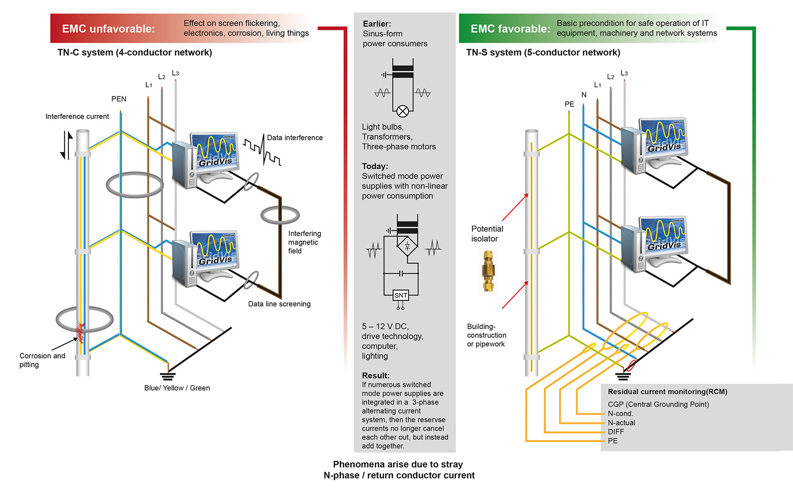
RCM measuring devices such as the UMG 96RM-E / UMG 509-PRO / UMG 512-PRO / UMG 20CM from Janitza are suitable for monitoring alternating currents, pulsing DC currents per IEC/TR 60755 (2008-01) and can be used for continuously checking for residual currents in TN-S systems.
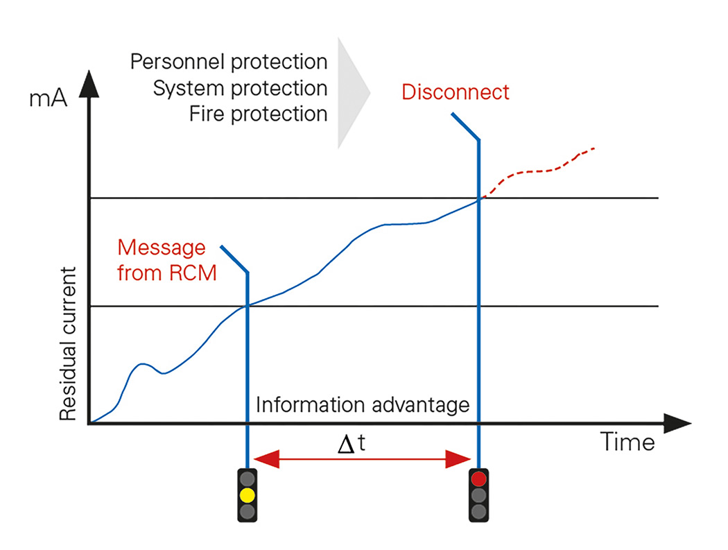
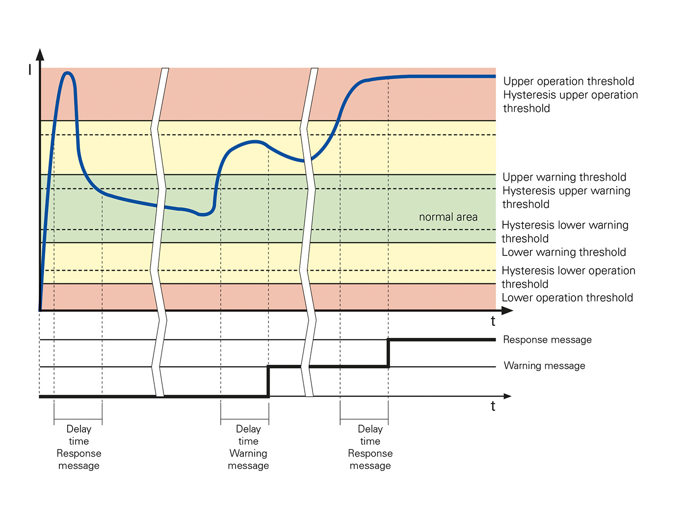
With a comprehensive RCM system, faults in TN-S systems are located directly. So that the user is able to react before a critical level is reached. It is also possible to avoid shut-downs due to residual current circuit breakers (RDCs). This applies in particular to quietly rising residual currents (e.g. triggered by an insulation fault), overly high operating currents or any other overloading of system parts and consumers (image 2).
RCM – the functionality
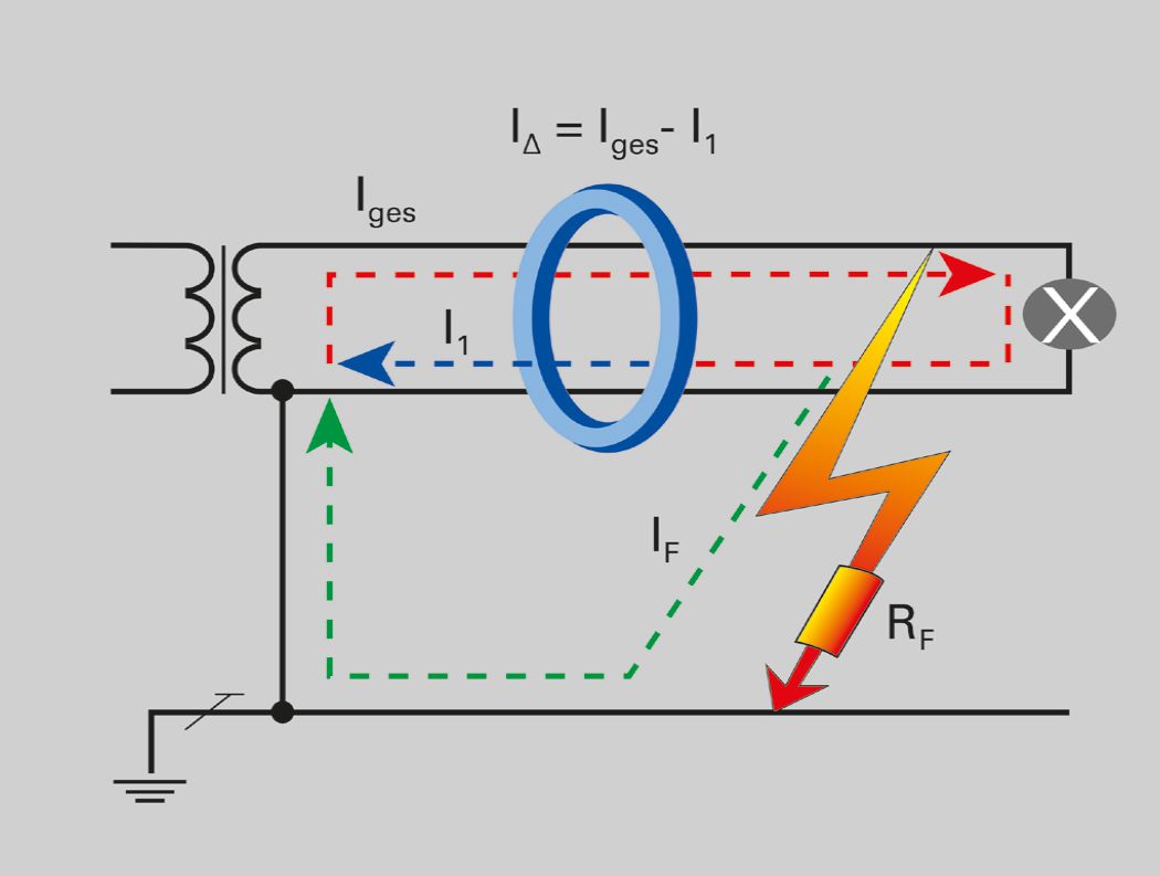
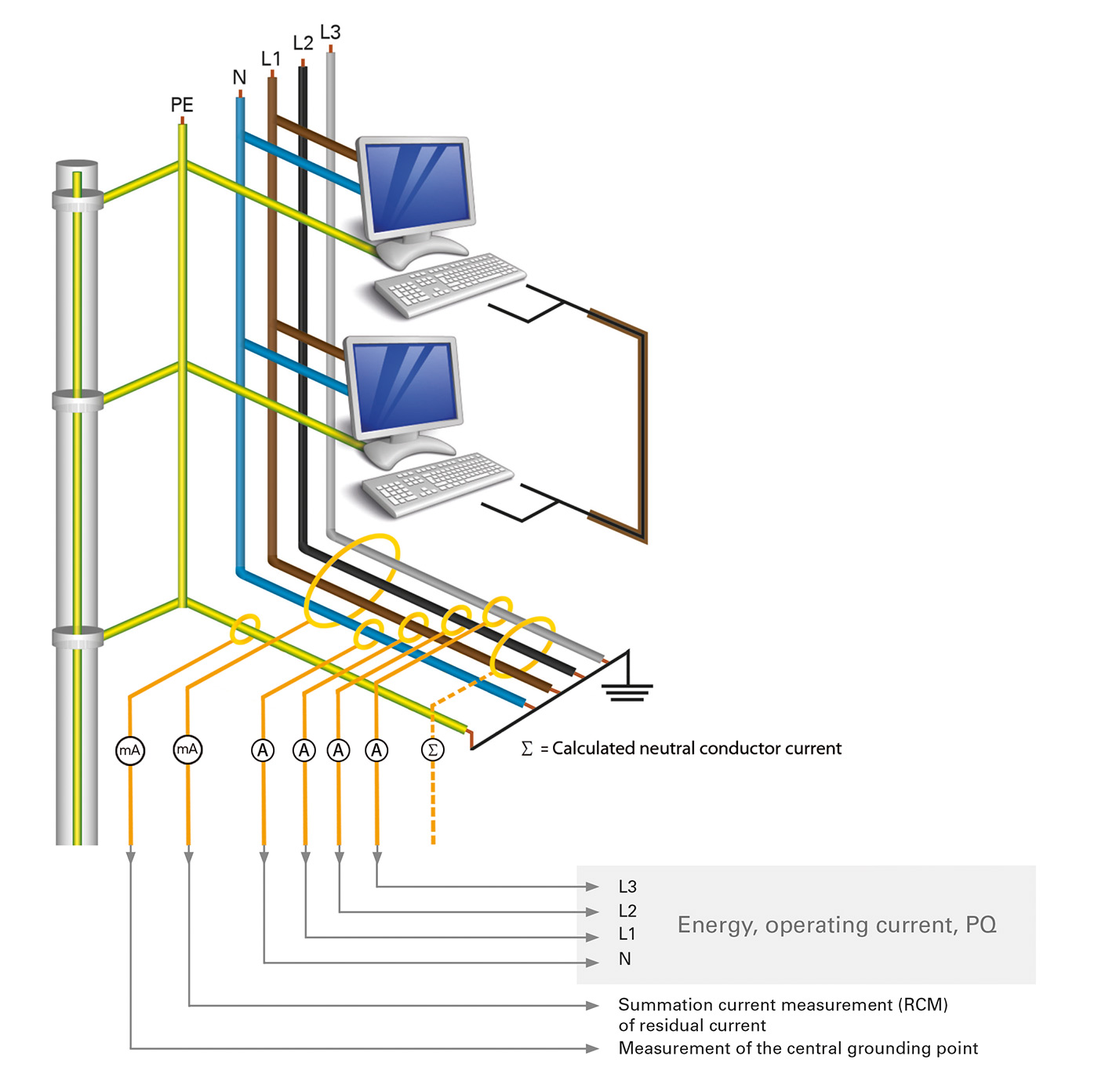
The basic functionality of the residual current principle is shown in image 3. Here, the phase and neutral conductor of the protected output are fed through the summation current transformer, the ground wire is left out. The image provides a better overview due to the highly simplified wiring. In practical terms, all three phases and the neutral conductor run through the summation current transformer. In case of systems without a neutral conductor, for example with controlled drives, only the three phases run through the summation current transformer.
If the system is in fault-free condition, the summation current is zero or close to zero (within a tolerable range), meaning that the current induced in the secondary circuit is also zero or close to zero. If, however, residual current flows away to ground due to a fault, the current differential in the secondary circuit will result in a current being logged and evaluated by the RCM measuring device (image 4).
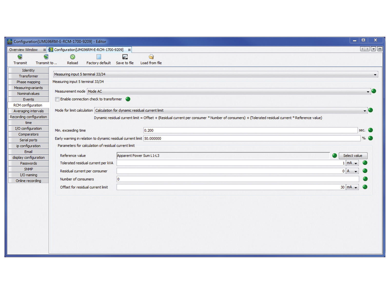
Modern RCM measuring devices accept different threshold value settings here (image 5). A static threshold value has the disadvantage that it is either too high with a part load, or too low with a full load, i.e. either insufficient protection is provided or erroneous alarms are issued, which may have negative effects on the attentiveness of the monitoring personnel over time. For this reason it is advisable to use RCM measuring devices with dynamic threshold value formation. In this case the residual current threshold value is formed on the basis of the actual load conditions and is therefore optimally aligned with the respective applicable load (image 6).
Through parameterisation (i.e. stipulation of the typical residual current in "GOOD" condition) of the system in new condition and constant monitoring, all changes to the system state after the point of start-up can be detected. This also enables detection of creeping residual currents. On the basis of historic progressions of the load and residual current, it is possible to determine the “GOOD” condition and define an expedient residual current threshold value. Integrated measuring device storage and superimposed SCADA systems or the energy data acquisition software GridVis® facilitate chronological statements and analyses.
RCM in practice
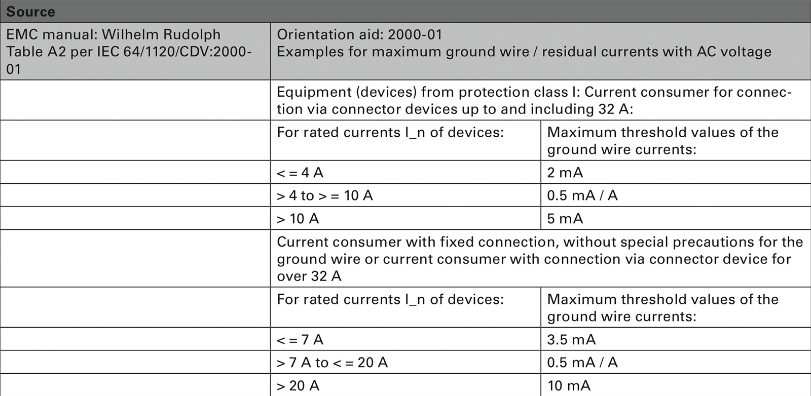
Listing every standard and specification that has been written in relation to RCM would go beyond the purpose of this contribution. However, a number of general rules do serve as starting points: For example, work with individual current circuits should continue to take place with fixed threshold values such as 30 mA, or with a fire protection objective with 300 mA. With frequency converters, the maximum residual currents in the datasheets should not be exceeded. The following always applies: Threshold values are empirical values, and must be stipulated depending on the type of consumer. Orientation aids are provided by works such as the EMC manual from Wilhelm Rudolph (image 7).
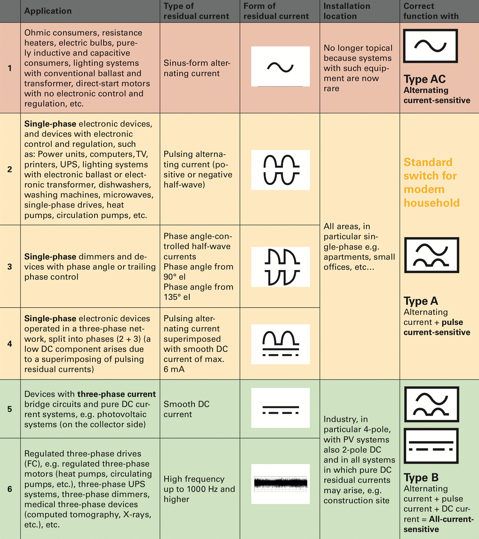
It is also necessary to select the right residual current acquisition equipment. The table in image 8 provides an overview.
The challenge of high availability
A typical application for RCM systems is the computer centre. IT technology itself places high demands on the supply, frequently even requiring high availability, i.e. an availability of at least 99.9 %. However, particularly critical are applications in which the loss of data simply cannot be allowed to occur. BITKOM therefore writes the following in its guidelines for "Operationally reliable computer centres": “In computer centres the maximum availability requirements apply. The energy supply must therefore be permanently guaranteed. Therefore comprehensible is the requirement that the power supply to the computer centre itself, and to all areas in the same building to which data cables run, must be designed as a TN-S system. Essential for assured operation is permanent self-monitoring of a “clean” TN-S system and the issue of signals to a permanently manned desk, e.g. in the control centre. The electrician then ascertains the action requirement based on the respective signals, and is able to prevent damage through targeted service measures. With the Janitza complete solution, it is possible to realise the safety criterion "RCM residual current monitoring" of this type of EMC-optimised TN-S system (image 9).
Reduced testing costs with RCM
RCMs not only ensure the maximum in safety, they also help to reduce costs. Recurrent testing, as prescribed for example in DGUV V3“Electrical systems and operating equipment”, is time-intensive and therefore costly. RCM monitoring systems reduce test costs and save time, whilst also ensuring increased safety. Fixed electrical systems and operating equipment are considered to be monitored constantly if they are permanently maintained by electrical engineers and tested by measuring equipment within the framework of operations (e.g. monitoring of the insulation resistance). Through permanent RCM measurement, monitoring systems are able to deliver the required degree of constant testing.
Potential savings:
- Reduction in the test costs due to omission of the insulation measurement
- Avoiding a system shut-down enables constant operation
- No shut-down of sensitive consumers, which could be damaged by a high test voltage
- No high personnel costs and administration work due to shut-downs
- Permanent testing for residual currents = improvement in EMC and minimisation of faults in controls and data lines
Under certain preconditions, it is also possible to avoid RCDs with continuous RCM monitoring. These are:
- Signal connection and immediate reaction in case of a fault
- Function testing of the signalling equipment
- Electrician on site
- Plugs inaccessible to laypersons
The following always applies: Residual current monitoring devices (RCMs) are not protective devices, however they may be used to monitor residual currents in electrical systems. Residual current monitoring devices (RCMs) emit an audible or an audible and visible signal if the predefined residual current value is exceeded.
(See: VDE 0100-410 415.1 and 411.3.3 / VDS2349 and 2046 / TRBS1201 / DGUV V3 / New draft standard for recurrent testing DIN VDE 0100- 600:2015-05 / IEC 60364-6)
Particularly noteworthy here is that RCM renders the cost-intensive measurement of insulation resistances at least partially superfluous, whilst constant testing of the insulation characteristics takes place. In order to carry out conventional insulation measurements, fixed systems and consumers must be switched off.
Furthermore, there is a risk that the high test voltage used for the insulation measurement may damage sensitive electronic components. The test accuracy and scope can be significantly reduced by constant monitoring. However, this must be determined on an application- specific basis. Acceptance and risk evaluation of comprehensive RCM monitoring by an expert or the employers' liability insurance association is advisable, although not mandatory.
It is also explicitly noted at this point that the following work must be carried out despite constant RCM measurement:
- Visual inspection for externally visible defects
- Protective measures and switch-off conditions
- Loop resistances and testing of the continuity of ground wires
- Function tests
Association of insurers requires RCM
The VdS has said the following on the subject of power supply systems: "In the case of power supply systems with PEN phase, operational currents - which may cause damage - flow through the entire ground and potential equalisation system (see section 3.3). With new electrical system installations it is therefore necessary to plan TN systems as TN-S systems. In the case of existing TN-C systems, modification to a TS-S system is advised. TN-S systems must be realised from the supply (handover) point where possible.
In order to guarantee the functionality of a TN-S system on a permanent basis (no conductor short between the N and PE phase, interchanging of the N and PE phase) this must be monitored by a residual current measurement device (RCM).
If the set trigger value is reached, a perceivable optical and acoustic error signal must be issued, in order that the defect can be eliminated immediately. In order that signal issuance is successful, this should be sent to a manned desk where applicable. If signalling is dispensed with then the forced shut-down of the faulty current circuit is required..."
Planning residual current monitoring
Planning can be roughly divided into the following steps:
- Risk estimation
- Stipulate measuring points (with residual currents, it must be possible to quickly locate fault sources)
- Construct measurable distribution systems
- Label CGP and test points clearly
- Stipulate, document and set threshold values
- Stipulate two autonomous signal routes (signal on site, signal in a permanently manned control centre)
- Test signal routes by imprinting faults (function testing)
- Train personnel on site (actions in case of a fault)
- Acceptance by an expert is advisable
Summary and outlook
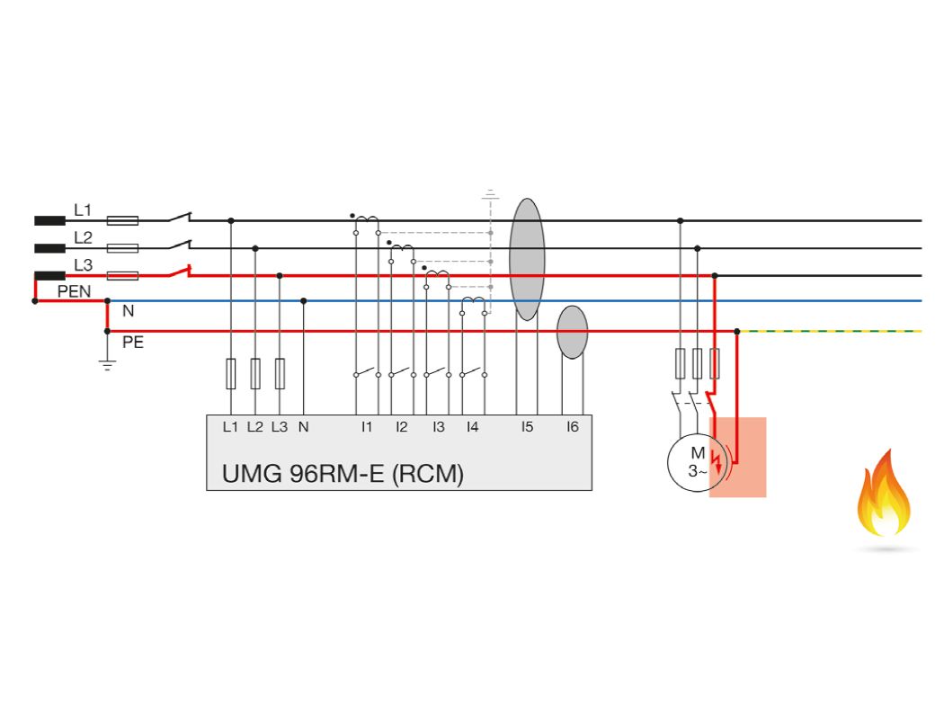
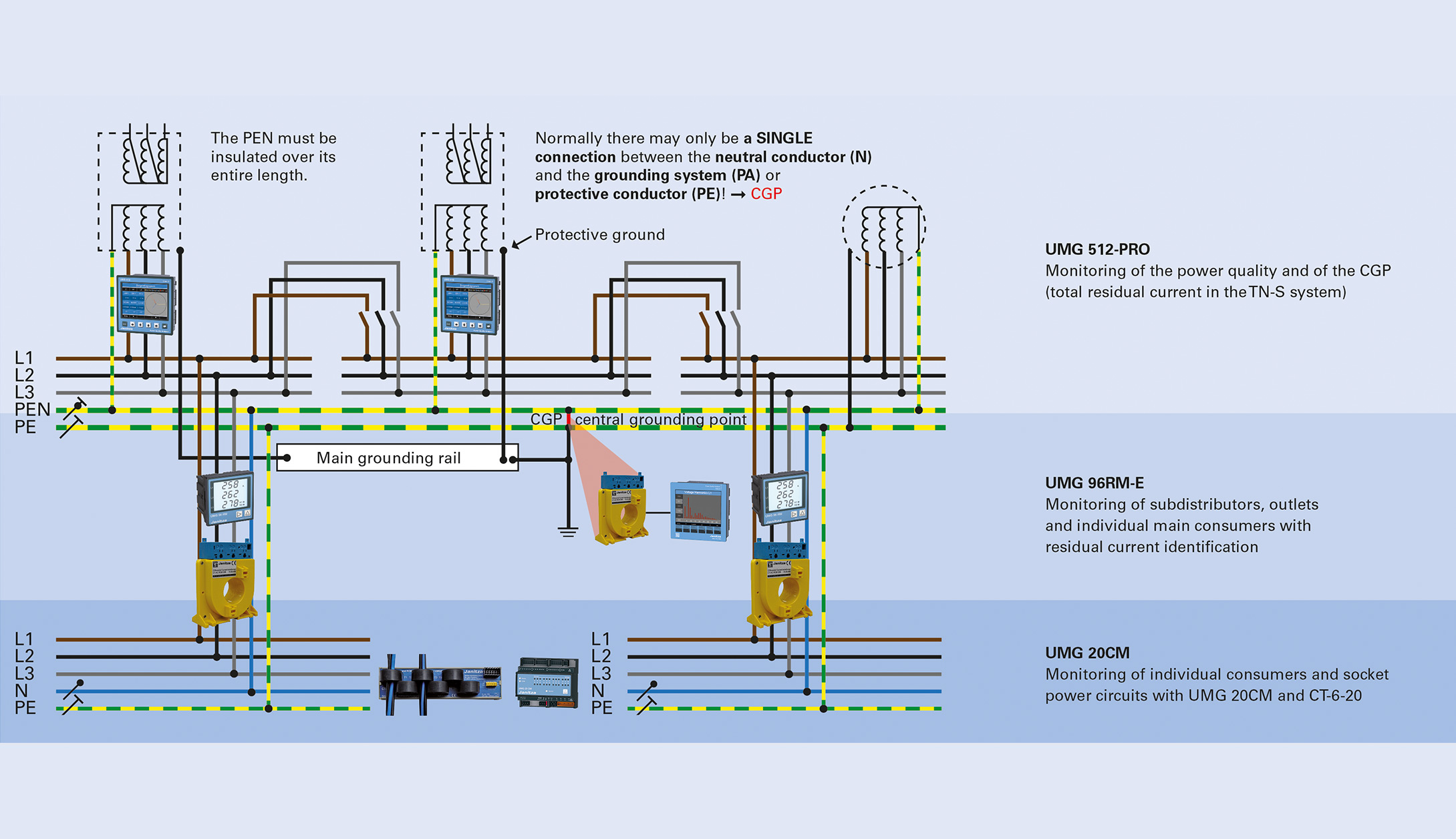
Comprehensive RCM monitoring of the power supply takes place at all levels: From CGP and outputs requiring monitoring in the LVDS and sub-distribution systems, right through to individual critical loads (image 10).
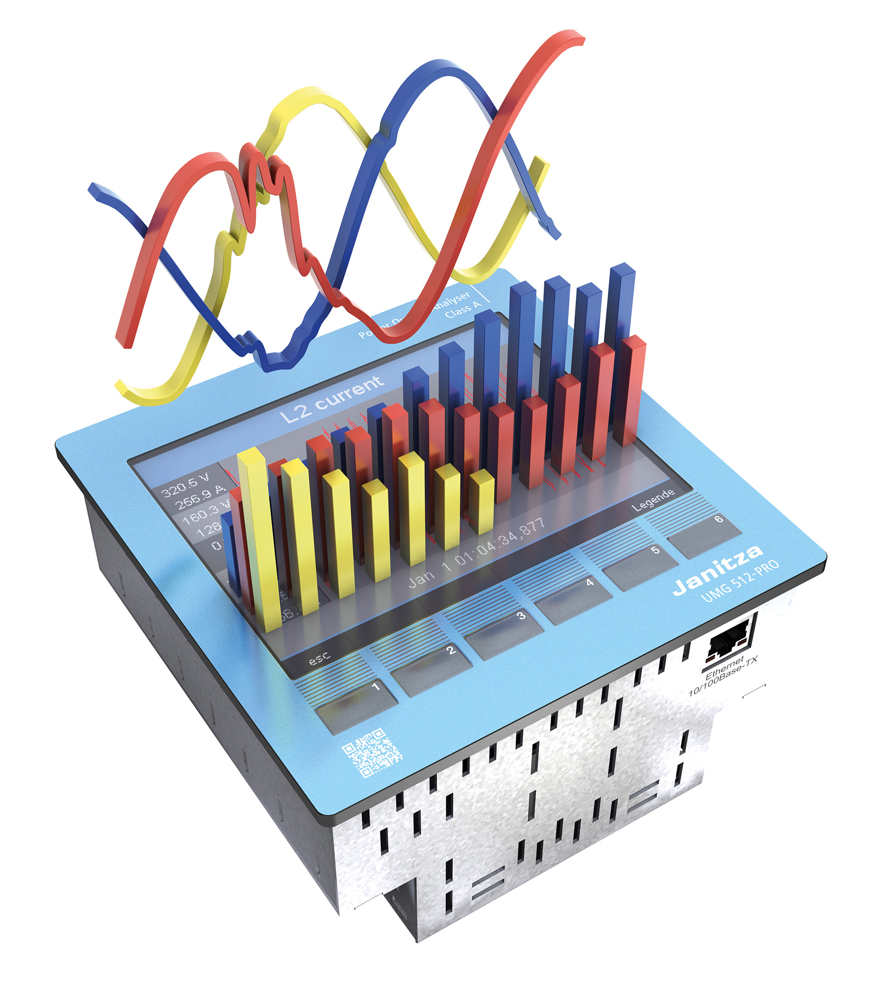
However, RCM is a monitoring measure through which to ensure a reliable power supply. Janitza has its UMG 512- PRO (image 11), UMG 96RM-E and UMG 20CM series for this. Together with the GridVis® energy data acquisition software and the integrated alarm management, solutions for three areas are united within a common system environment and just one measuring device per measurement point:
- Energy management according to ISO 50001 (acquisition of V, A, Hz, kWh, kW, kVArh, kvar ...)
- Power quality monitoring (harmonics, flicker, voltage dips, transients, etc.)
- Residual current monitoring RCM
This consolidation of the three different functions within a single measuring device brings with it the major advantage that both the assembly and installation, as well as the remaining infrastructure (current transformer, communication lines and equipment, database, software, analysis tools and reporting software, etc.) are only required once. Furthermore, all data is logged centrally in a database and can be conveniently processed with a single software application, which in turn significantly increases the acceptance among users.
Article author

Gerald Fritzen
Keyaccount Manager
data center
gerald.fritzen@janitza.de
+49 5234 2041439 (Phone)
Source references:
- VdS (Association of Insurers)
- DIN VDE standards
- BG: DGUV Specification 3 Electrical systems and operating equipment (BGV A 3)
- ((Image Source)) Janitza electronics GmbH