
HIGH AVAILABILITY THROUGH CONSISTENT MONITORING

Whereas a brief power dip might have caused nothing more than a flicker in the lights years ago, today it can bring entire operations to a standstill. That is why precise monitoring of the power supply is essential. After all, disruptions arise not only in the power grid but also within a company’s own infrastructure. Continuous monitoring detects anomalies early on. Ideally, faults can be detected before they lead to a failure. This does not require many individual systems: a modern monitoring system collects the relevant data centrally.
Highly automated manufacturing facilities, data centers, and continuous processes rely on a reliable power supply—often even on high availability, i.e., an availability of at least 99.9%. The numerous servers, systems, storage media, and network components have little tolerance for voltage sags or other deviations in voltage quality from the standard (e.g., EN 50160).
This applies to information and communication technology as well as various infrastructure functions such as air conditioning, fire protection, EMC, security systems, lighting, elevators, and drives.
Power Quality
Power quality describes the quality of the electrical supply and any disturbances to it, such as harmonics, flicker, transients, or voltage sags. It is crucial for the stable operation of sensitive equipment and IT infrastructure.
Learn more about power quality
Integrated Measurement Technology
It goes without saying that a reliable power supply is a top priority in high-availability applications. Energy efficiency, however, remains an important goal. Integrated measurement technology supports both of these requirements. It facilitates energy management and monitors voltage quality and residual current within a single system. This makes it easier to collect, analyze, and document measurement data. At the same time, anomalies can be detected earlier.
Janitza offers tailored solutions for various measurement levels. These include the UMG 512-PRO, the UMG 96RM-E, and the UMG 801. Together with the GridVis® grid visualization software and alarm management, all necessary measurements can be performed within a single system environment.

Smart Monitoring
Integrated monitoring combines three functions into a single solution:
- Energy management using the relevant energy data in accordance with ISO 50001 (measurement of V, A, Hz, kWh, kW, kVArh, kvar, etc.)
- Monitoring of power quality, such as harmonics, flicker, or voltage sags
- Residual current monitoring (RCM)
Combining these functions in a single measuring device simplifies the setup and operation of the measurement system. This simplifies integration and reduces technical effort. The measurement data is centrally recorded, evaluated, and documented in a software application. Users work with a shared database and within a unified software environment. Because only one system is used, no additional interfaces between different solutions are necessary. This also makes it easier to organize training and onboarding.

Notify Before Absence
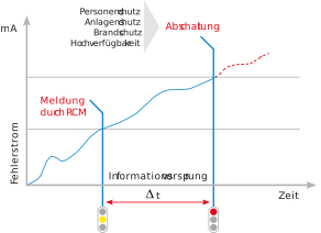
A key advantage of integrated data collection is its speed and the comprehensive overview it provides of all data. This makes it possible to detect malfunctions that a single system would only partially detect—or not at all. As a result, the user can take action before fuses or residual current devices (RCDs) shut down affected systems or outlet circuits. This applies in particular to excessively high operating currents, overloaded loads, and gradually increasing residual currents—for example, due to insulation faults.
Another source of faults is significant power grid disturbances or resonance phenomena caused by a growing number of nonlinear electrical loads. If irregular grid parameters—such as excessive harmonics or fault currents—are detected in time, corrective measures can be initiated before a device fails. This helps prevent downtime or, at the very least, plan for and reduce it.

Security, Fire Safety and High Availability
Residual Current Monitoring (RCM) is crucial for high-availability power supplies. Continuous processes and particularly sensitive applications—such as data centers, hospitals, and semiconductor factories—rely on RCM. Even in situations where insulation resistance measurements and ground-fault circuit interrupters cannot be implemented due to local or operational constraints, continuous RCM monitoring offers a viable alternative. Predictive monitoring also reduces the number of alarms, as required, for example, by alarm management standards such as EEMUA 191 or NAMUR NA 102.
Residual Current Monitoring (RCM) can also reduce the risk of fire. A residual current caused by defective insulation can be treacherous. The magnitude of the current is determined by the power of the supply network, the insulation fault resistance, and the ground resistance. The upstream protective device disconnects the electrical load from the network when the current flow is sufficiently high—for example, in the event of a full earth fault or a correspondingly low-resistance short circuit. If the fault current is too small, the protective device does not trip. However, even with a recorded fault power of about 60 watts—corresponding to approximately 261 mA at 230 V—there is a fire hazard. Residual current monitoring thus also serves to prevent fires.

RCM – How it works
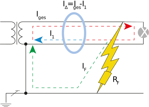
The basic operation of the residual current principle is shown in Image 2. The phase and the neutral conductor of the outgoing circuit to be protected are routed through the summation current transformer, the protective conductor is excluded. The image shows a simplified circuit for a better overview. In practice, all three phases and the neutral conductor run through the summation current transformer. When the system is in the fault-free state, the summation current is zero or close to zero (within the tolerance range), so that the current induced in the secondary circuit is also zero or close to zero. If, on the other hand, a residual current flows to ground in the event of a fault, the current difference in the secondary circuit causes a current that is detected and evaluated by the RCM measurement device (Image 3).
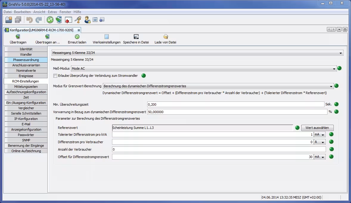
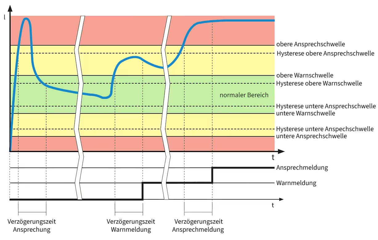
Modern RCM devices allow different limit value settings (Image 4). A static limit value has the disadvantage that it is either too large at partial load or too small at full load, i.e. there is either insufficient protection or false alarms occur, which can have a negative effect on the attention of the monitoring personnel in the long term. For this reason, it is recommended to use RCM measurement devices with dynamic limit value adaptation. In this case, the residual current limit value is formed on the basis of the current load conditions and is therefore optimally adapted to the load in question (Image 5).
By parameterizing (i.e. defining the typical residual current in the "GOOD" state) the system in the new state and continuous monitoring, all changes in the system state can be identified from the time of initial commissioning. This can also be used to detect creeping residual currents.
Figure 2 shows a greatly simplified illustration of how the residual current principle works. In practice, all three phases and the neutral conductor pass through the total current transformer, and their currents are summed. When the system is fault-free, the phase currents and the neutral conductor current balance each other out. As a result, the total current is zero or close to zero—that is, within the tolerable range. Accordingly, the current induced in the secondary circuit is also zero or close to zero. If a fault current to ground flows in the event of a fault, the current difference generates a total current, which in turn generates a current in the secondary circuit. The RCM meter detects and evaluates this current.
RCM
RCM stands for Residual Current Monitoring and refers to the continuous monitoring of residual currents in electrical systems. This allows for the early detection of insulation faults, leakage currents, and other anomalies.
Learn more about RCM.
Modern RCM devices allow for different threshold settings. A static threshold has the disadvantage that it may be too high under partial load and too low under full load. As a result, either insufficient protection is provided or false alarms occur. Over time, this can have a negative impact on the vigilance of monitoring personnel. For this reason, RCM meters with dynamic threshold adjustment are particularly well-suited. They calculate the residual current threshold based on current load conditions and thus adapt
New technology, new sources of error
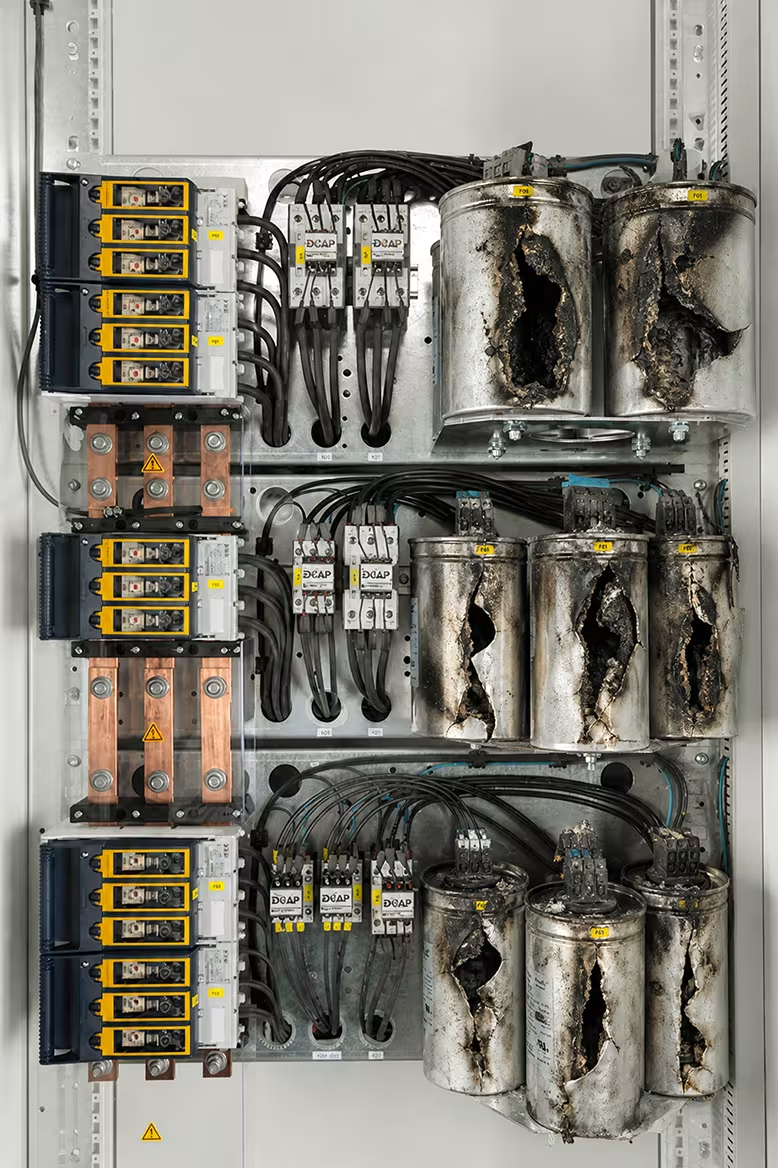
Collapsing polypropylene phase-shifting capacitors are an example of "modern sources of error". These are used to compensate for reactive currents, such as those caused by three-phase motors.
Paradoxically, a fault is therefore caused by a device that is actually intended to improve the energy supply. The PP windings of these capacitors often melt due to overload or overtemperature. The melting mass then causes a high-impedance ground fault. Such ground faults cannot be switched off by conventional protective measures (NH fuse, circuit breaker). The continuous residual current usually leads to a saturated short circuit in the medium term and can then pose a considerable fire or safety risk under certain circumstances (Image 6). Residual current measurement detects such faults and allows rapid countermeasures to be taken. This prevents costly and dangerous system failures.
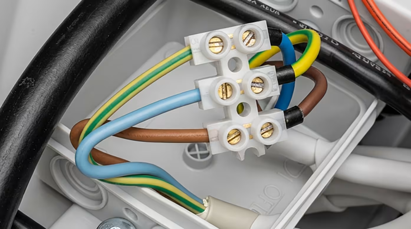
Faults often occur during installation, such as impermissible connections between the N and PE conductors. Sometimes the two are simply interchanged. Image 7 shows a typical connection fault, which can easily result in a residual current of 5000 mA. With RCM, such faults are detected immediately during the installation phase and reported via the alarm management system.
Another, more novel source of interference is a large number of single-phase loads, such as switching power supplies for servers in data centers or PCs in office buildings. They cause a high proportion of 3rd harmonics currents. These harmonic components have the major disadvantage that they are superimposed on the neutral conductor instead of canceling each other out via the transformer windings. The N conductor may be overloaded. Integrated measurement devices, such as the UMG 96RM-E, allow comprehensive monitoring of all phases and can therefore report excessive neutral conductor currents in good time.
In this context, it is also important to mention the safety regulations of the VdS (Association of Property Insurers) for electrical systems up to 1000 volts:
"VdS 2046: 2010-06 (11) 3.2.4 In order to increase safety in electrical installations in which numerous non-linear consumers (such as frequency converters, phase angle control systems, e.g. in lighting systems) are operated, the current in the neutral conductor must be measured regularly, e.g. once a year, and also after significant changes to the electrical installation or the type and number of electrical consumers. If the safety of the system is endangered by excessive harmonics currents, measures must be taken to protect against harmonics in accordance with the publication "Low-noise electrical installation" (VdS 2349)."
One example of modern sources of faults is the failure of polypropylene phase-shifting capacitors. They are used to compensate for reactive currents, such as those generated by three-phase motors.
In these capacitors, the PP windings often melt due to overload or overheating. The molten material then causes a high-resistance ground fault. Such ground faults cannot be interrupted by conventional protective measures such as NH fuses or circuit breakers. The continuous fault current typically leads to a full short circuit in the medium term and can then, under certain circumstances, pose a significant fire or safety risk (Figure 6). Residual current detection identifies such faults and allows for rapid corrective action. This helps prevent costly and dangerous system failures.
Errors often occur as early as the installation phase, such as improper connections between the N and PE conductors. Sometimes the two are simply swapped. Figure 7 shows a typical connection error that can easily result in a fault current of 5,000 mA. With RCM, such errors are immediately detected during the installation phase and reported via the alarm management system.
Another source of interference is a large number of single-phase loads, such as switching power supplies for servers in data centers or PCs in office buildings. They generate a high proportion of third-harmonic components.
These harmonic components have the major disadvantage that they superimpose on the neutral conductor rather than canceling each other out through the transformer windings. This can lead to overloading of the neutral conductors. Integrated measuring devices, such as the UMG 96RM-E, monitor all phases comprehensively and can report excessive neutral conductor currents in a timely manner.
In this context, the safety regulations of VdS Schadenverhütung for electrical systems up to 1,000 volts should also be mentioned.
VdS 2046 : 2010-06 (11)
3.2.4 To increase safety in electrical systems in which numerous nonlinear loads (such as frequency converters, phase-angle-controlled systems, e.g., in lighting systems) are operated, the current in the neutral conductor must be measured regularly—e.g., once a year—as well as after significant changes to the electrical system or the type and number of electrical loads. If the safety of the system is compromised by excessively high harmonic currents, measures to protect against harmonics must be taken in accordance with the publication “Low-Interference Electrical Installation” (VdS 2349).



The challenge of high availability
IT technology places high demands on the power supply. Applications in which data loss is absolutely unacceptable are particularly critical. Today, EN 50600 is considered the authoritative standard for data centers.
An EMC-optimized TN-S system is also particularly important. Undesired connections between the neutral (N) and protective earth (PE) conductors, creeping insulation faults, or abnormal residual currents can compromise operational safety and should therefore be detected early. Continuous monitoring provides transparency and makes critical conditions visible even before a failure occurs.
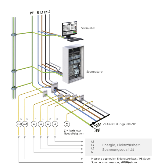
The Janitza solution enables reliable RCM residual current monitoring in an EMC-optimized TN-S system (Figure 8).
Reduce inspection costs with RCM
Recurring inspections, such as those required by DGUV V3 “Electrical Installations and Equipment,” are time-consuming and therefore costly. For conventional insulation testing, for example, stationary systems or loads must be shut down and the neutral conductor disconnected. Additionally, there is a risk that the high test voltage used in insulation testing could damage sensitive electronic components. However, the frequency and scope of testing can be reduced through continuous monitoring.
This is because stationary electrical systems and equipment are considered to be under constant monitoring if they are continuously maintained by qualified electricians and tested through metrological measures as part of normal operations.
RCM provides such continuous monitoring of insulation condition. This allows operators to avoid some of the cost-intensive insulation resistance measurements.
However, this must be determined on a case-by-case basis. Consultations with the operator—and, if necessary, with experts and/or the workers’ compensation association—are absolutely essential for this purpose.
It should be explicitly noted here that the following work must be performed despite continuous RCM monitoring:
- Visual inspection for externally visible defects
- Protective measures and shutdown conditions
- Loop resistances and continuity testing of protective conductors
- Functional testing

The Association of Property Insurers Calls for RCM
The VdS comments on the topic of harmonics and the installation of power supply systems as follows: “In power supply systems with a PEN conductor, operational currents flow throughout the entire grounding and equipotential bonding system, which can cause damage (see Section 3.3). For new electrical installations, TN-S systems should therefore be planned instead of TN systems. For existing TN-C systems, conversion to a TN-S system is recommended. TN-S systems should be implemented starting at the feed-in point (transfer point) whenever possible. To ensure the long-term functionality of a TN-S system (no short circuit between the N and PE conductors, no reversal of the N and PE conductors), it must be monitored by a residual current monitoring device (RCM). If the set response threshold is reached, an audible and visual fault signal must be triggered so that the defects can be rectified immediately. To ensure the signal is effective, it should be routed to a staffed location if necessary. If the signal is not routed to a staffed location, the faulty circuit must be automatically shut down …”
Elsewhere, in the safety regulations for electrical systems up to 1,000 volts, the VdS stipulates: “VdS 2046: 2010-06 (11)
3.2 Maintaining Proper Condition
3.2.3 To ensure the long-term safety of electrical installations, if insulation resistance measurements cannot be performed due to local or operational conditions, alternative measures must be taken. Such measures are described in the publication “Protection Against Insulation Faults” (VdS 2349).” An adequate alternative measure here is continuous RCM monitoring!
Energy measurement and standard electrical parameters
RCM plays an important role in equipment monitoring through the Janitza system. However, other aspects must not be overlooked. In addition to a reliable energy supply, energy efficiency is also more relevant than ever. ISO 50001 provides the normative basis for implementing an energy management system. The focus here is on the concept of a management system. Following the model of other management systems such as ISO 9001 or ISO 14001, the goal is to set objectives, implement them systematically, and eliminate the element of chance as much as possible.
With Janitza’s UMG meters and GridVis® grid visualization software, users can record and analyze standard electrical parameters as well as power and energy consumption.
Monitoring power quality
The reliable operation of modern equipment and systems always requires a high level of supply reliability and good power quality. In modern power supply systems, numerous single- and three-phase nonlinear loads are used. These include lighting technology—such as dimmers for spotlights or energy-saving lamps—numerous variable-frequency drives for heating, air conditioning, and ventilation systems, variable-frequency drives for automation technology or elevators, as well as the entire IT infrastructure with its regulated switching power supplies. In many locations, inverters for photovoltaic (PV) systems and uninterruptible power supplies (UPS) are also found.
All of these nonlinear electrical loads cause grid disturbances of varying severity and distort the originally “clean” sine wave. As a result, the current and voltage waveforms are distorted accordingly (Figure 10 and Figure 11).
The load on the grid infrastructure caused by electrical and electronic loads that generate grid disturbances has increased significantly in recent years. This results in various grid disturbances and disturbances, depending on the grid stiffness at the connection point, the relative size of the nonlinear loads, and the type of generation system and equipment, e.g., grid injection via a converter or generator. To ensure a reliable power supply in data centers, power quality must comply with EN 61000-2-4 (Class 1).
Janitza uses a wide range of power quality analyzers to measure and analyze the various parameters of voltage quality. Standardized voltage quality reports in the GridVis® software enable the generation of reports in accordance with common standards, such as EN 50160, EN 61000-2-4, and ITIC (“CBEMA curve”).


Monitoring solutions in practice
For a comprehensive monitoring solution, energy, power quality, and RCM are measured using a single meter. To do this, it measures all conductors (L1, L2, L3, N) as well as the central grounding point (ZEP) and RCM.
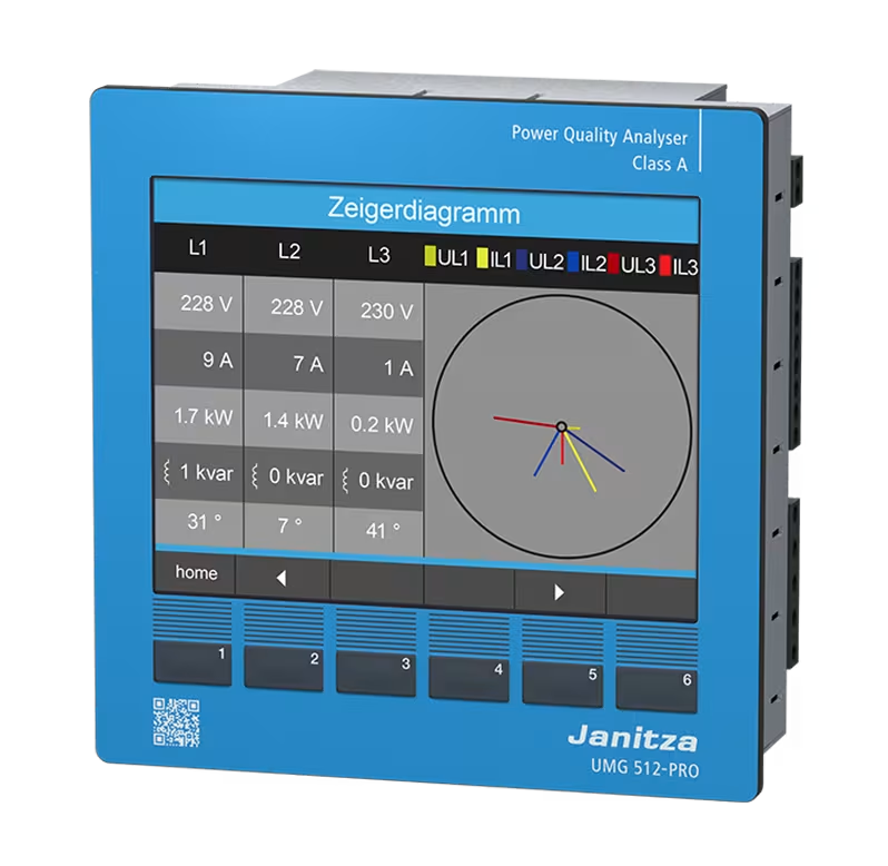
High-performance meters for comprehensive monitoring include the UMG 96RM-E and the UMG 512-PRO. The UMG 96RM-E features six measurement inputs and is ideal for intermediate distribution panels. The UMG 512-PRO is primarily used at main nodes and the CGP and is Class A certified. The measuring devices can be easily integrated into existing communication networks via Ethernet. Numerous IP protocols, the device’s web interface, and the SNMP protocol simplify administrators’ work.
In complex electrical installations with a large number of measurement points, the modularly expandable UMG 801 network analyzer is the ideal solution. These meters measure line current and residual current and can be expanded with a wide range of modules. Users can analyze power quality with them. Thanks to numerous protocols, such as OPC UA, and a variety of interfaces, it can be easily integrated into existing systems.
With special cable conversion adapters for line current and residual current, users can retrofit existing systems cost-effectively without having to shut down electrical loads.


Alarm in the right place
Alarms must not go unheard. An audible signal from the control cabinet in the main distribution panel is of little use in the control room.
The GridVis® software offers comprehensive notification options for alarm management. This ensures that notifications from the integrated RCM measuring devices quickly reach the correct recipient. With customizable escalation levels and a logbook function, the monitoring control room has all the tools it needs for efficient monitoring. The responsible qualified electrician can quickly detect and evaluate increases in residual current and initiate maintenance measures as needed.
Vagrant currents disturb the EMC
Connections between the N and PE conductors cause “stray” operating currents to spread through the PE system, data lines, and all metal parts of the building. Because these currents are not balanced, they generate electromagnetic fields. This results in a wide range of disturbances in electrical systems, computer networks, and piping systems within the building. Figure 12 illustrates how the operating current is distributed at the PEN bridge and can flow back via multiple paths. As a result, the sum of the current in the supply and return conductors is no longer 0. This can lead to the following malfunctions:
- Changes in the operational behavior of frequency-dependent components, such as increased current draw by capacitors
- Interference with data transmissions due to magnetic and inductive influences
- Transmission of lightning surges into the electrical system
- Corrosion on metallic conductors
- Adverse effects on people
The supply and return conductors should also be arranged close together in distribution panels. This minimizes magnetic fields. At every junction in a circuit, the sum of the currents must equal zero to prevent fault currents. In addition, the sub-distribution panel or circuit should be monitored consistently. The UMG 96RM-E monitors sub-distribution panels and larger loads and detects residual current. This ensures that fault currents are detected immediately and malfunctions can be prevented.
Individual circuits in which residual current circuit breakers cannot be installed due to operational requirements can be monitored with the UMG 801. Continuous residual current monitoring with alarms, combined with on-site qualified personnel, provides maximum alternative safety.
Neutral conductor and CGP
The neutral conductor (operating current return conductor) is the most important conductor today. It must be treated like an outer conductor. To ensure that the grounding system remains “clean,” the current-carrying N conductor must be located far away from the PE conductor. No galvanic operating currents are allowed to flow through the grounding system, as these would cause inductive coupling. These measures must be implemented all the way back to the power source.
In the TN-S system, the N conductor is connected to the grounding system and monitored only once, at the so-called ZEP (central grounding point from N to PE), at a suitable location. Undesirable insulation faults or galvanic connections between N and PE are immediately detected by monitoring the ZEP. Deviations are reported in a timely manner, and temporal dependencies are analyzed.
With the UMG 512-PRO, users can verify whether the TN-S system is functioning properly. It allows for a comprehensive assessment of power quality and EMC. For example, it even records the phase that triggers a ground fault and enables analysis. The phase current then rises in parallel with the ZEP current.
The current at the ZEP must always be considered in relation to the total power of the TN-S system. This means that, on the one hand, operational leakage currents are tolerated, but on the other hand, abnormal deviations at the ZEP are reported by the RCM.
Summary and Outlook
High demands are placed on the power supply, as outages result in significant costs. To ensure high availability, operators must keep an eye on the entire electrical infrastructure, not just individual fault patterns. Anyone seeking to ensure high availability must monitor the electrical infrastructure holistically. To do this, operators collect energy data, analyze voltage quality, and continuously monitor residual currents.
Janitza offers tailored solutions for various applications and measurement levels. The modular, expandable UMG 800 energy analyzer is particularly well-suited for measurement systems with many outputs and provides transparency regarding energy data and energy flows. The UMG 801 supports energy management systems in accordance with ISO 50001. It enables the analysis of voltage quality, thereby providing transparency across all measurement levels. For continuous power quality analysis and additional residual current monitoring, the UMG 512-PRO power quality analyzers, among others, are available. This allows for targeted monitoring and evaluation of the power supply—from the feed-in through main and sub-distribution panels all the way to individual loads.
TAILORED SOLUTIONS FROM JANITZA FOR COMPREHENSIVE MONITORING
For comprehensive monitoring to work effectively in day-to-day operations, it requires a well-thought-out measurement point strategy, clearly structured data, and analysis that leads to action. Janitza supports you every step of the way—from planning and implementation to maintenance.
GridVis®
With GridVis®, you can centrally visualize and analyze energy data and place measurement values in the proper context. This allows you to identify potential savings, optimize equipment usage times, and detect anomalies early on. The software consolidates measurement data across systems and supports the implementation of a scalable monitoring system for energy management, residual current monitoring, and power quality.
Learn more about GridVis®
Project Solutions
Project Solutions stands for customized, end-to-end solutions that combine measurement technology, software, automation, and project-specific implementation into an integrated system solution. This is particularly valuable when energy monitoring needs to be implemented quickly or when transparency is required in complex infrastructures. From planning through implementation to operation, Janitza provides comprehensive and practical support for your project process.
Learn more about Project Solutions
UMG 512-PRO
With the UMG 512-PRO, you can continuously monitor power quality and analyze electrical disturbances when anomalies occur in the grid. This is particularly important in applications where availability is critical. The Class A power quality analyzer provides a reliable data foundation. This enables users to pinpoint the causes of disturbances more quickly and take targeted corrective actions. In addition, the device enables residual current monitoring. This allows for the early detection of fault currents and transparent monitoring of the system’s condition. The UMG 512-PRO complies with Class A standards and measures all voltage quality parameters relevant to standards.
Learn more about the UMG 512-PRO
UMG 801
With the UMG 801, you can centrally collect energy data and ensure transparency across all measurement levels. This modular, expandable power analyzer is particularly well-suited for complex electrical installations with numerous measurement points. Thanks to OPC UA and other communication interfaces, the device can be flexibly integrated into higher-level systems. This creates a robust data foundation for monitoring, analysis, and optimization.
Learn more about the UMG 801