Operation of current transformers
Replacement of a measurement device (short-circuiting of current transformers)
The current transformer secondary circuit should not be opened under any circumstances if current is flowing in the primary circuit.
The output of the current transformer acts as a current source. As the load increases, the voltage output therefore increases (according to the relationship U = R x I) until saturation is reached. Above saturation, the peak voltage continues to rise with increasing distortion and reaches its maximum value with an infinitely large load, i.e. open secondary terminals. High voltage peaks can therefore occur with open transformers, which are a danger to people and can destroy the transformer and measurement device when reconnected.
This means that open operation must be avoided and unloaded transformers must be short-circuited.
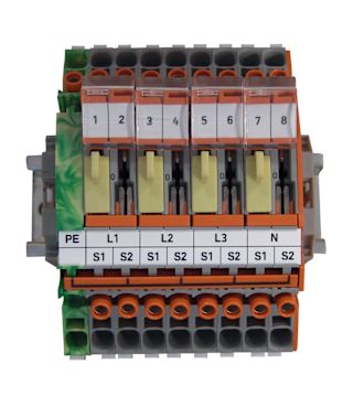

Current transformer terminal strips with short-circuit device
Special terminal strips for the DIN rail are recommended for short-circuiting current transformers and for the purpose of recurring comparative measurements. These consist of a cross-disconnect terminal with measuring and testing equipment, insulated bridges for grounding and short-circuiting the transformer terminal.
Overload
Primary current overload: Primary current too high --> Saturation of the core material --> Accuracy drops massively.
Nominal power overload: Too many measurement devices or too long cables are connected to a transformer with its defined nominal power --> Saturation of the core material --> Accuracy drops massively.
Short-circuit event
In the event of a short circuit, there is no longer a signal. The measurement device can no longer measure. Current transformers can (or must) be short-circuited if no load / burden (measurement device) is applied.
Operation with harmonics current
Our transformers generally measure harmonics currents up to 2.5 kHz (50th harmonic) and many types also up to 3 kHz and even beyond. At higher frequencies, however, the eddy current losses and thus also the heating increase. If the harmonics content becomes too high, current transformers with thinner laminations must be used.
However, it is not possible to make a general statement about a limit value for the harmonics content, as the heating depends on the core size, transformer surface (cooling), ambient temperature, transmission ratio, etc.
Own power consumption UMGs, energy meters, measurement devices
Measurement device type | Power consumption current measurement input in VA |
|---|---|
Analog amperemeter | 1.1 |
UMG 103 / 104 / 604 / 605 | 0.2 |
UMG 96RM | 0.2 |
UMG 96RM-E | 0.2 |
UMG 508 / 509 | 0.2 |
UMG 511 / 512 | 0.2 |
ECSEM series energy meters | 0.36 |
Power consumption UMG 96RM-E per current input
UMG 96RM-E | 0.2 VA |
+ | |
4 meter 2-wire cable 2.5 mm² | 1.43 VA |
= | |
Results in the power consumption of the measurement device | 1.84 VA |
Special use case: large transformer – small current
Tip: Select a current transformer that is suitable for measuring a nominal current of 50 A. To divide the normal current of a current transformer by two, it is actually sufficient to pass this current through the transformer twice.


