Voltage drops
Voltage drops can lead to huge problems – for example, to the drop-out of production processes and to product or process quality problems. Such voltage drops arise much more frequently than interruptions, however in many cases unidentified. The commercial effects of voltage drops are seriously underestimated time and again.
But what really is a voltage drop? How does a voltage drop arise? Can a voltage drop be prevented or must we try to limit the consequent damages through timely identification? These topics will be dealt with in more detail in this article.
What is a voltage drop?
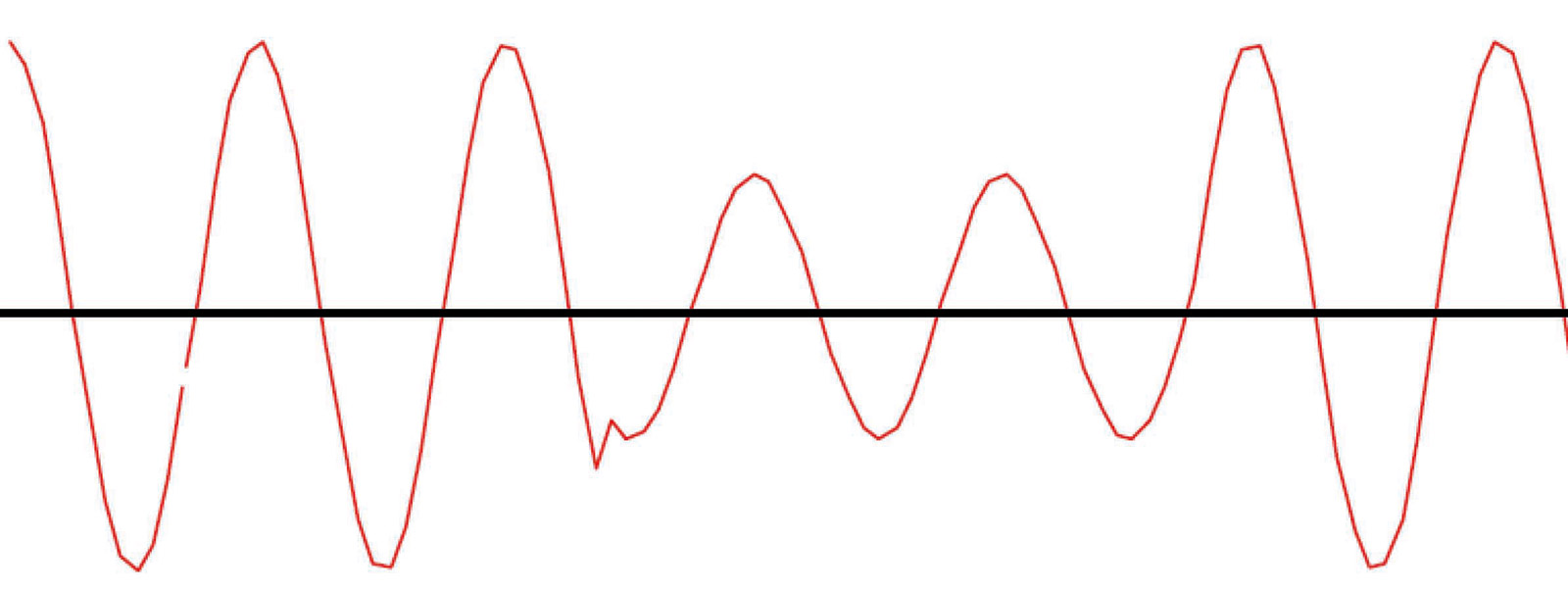
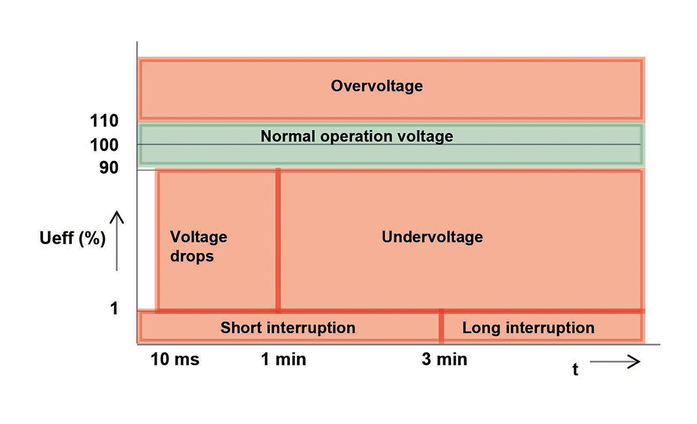
According to the European standard EN 50160 a voltage drop is a sudden lowering of the effective voltage value to a value of between 90% and 1% of the stipulated nominal value, followed by the “immediate” recovering of this voltage. The duration of a voltage drop lies between a half period (10 ms with 50 Hz grids) and one minute.
If the effective value of the voltage does not drop below 90% of the stipulated nominal value then this is considered to be normal operating conditions. If the voltage drops below 1% of the nominal value then this is considered a voltage interruption.
A voltage drop should therefore not be confused with an interruption. An interruption arises, for example, after a circuit breaker has tripped (typ. 300 ms). The mains power failure is propagated throughout the remaining distribution network as a voltage drop.
How does a voltage drop arise?
1. Starting currents
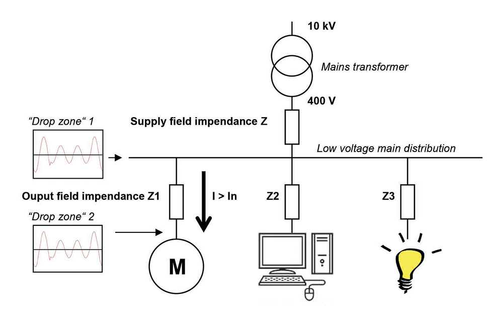
A known cause of small voltage drops are the starting or inrush currents for capacitors, motors and other devices. In the following diagram it can be seen that the current increases briefly when the motor starts up. The inrush current leads to a voltage drop across the impedances Z and Z1. However it leads to a smaller voltage drop at the low voltage bus bar (drop zone 1) and a somewhat larger voltage drop behind impedance Z1 (drop zone 2).
Possible improvement to this phenomenon lies in the optimisation of the system itself, i.e. the switching-on of electrical loads should not lead to critical voltage drops. Typical solutions are adequate starting equipment, e.g. capacitor contactors for PFC or soft starters for motors, but it can be as well the increase of short circuit power (reducing impedance), e.g. larger cable cross section, changing the connection point to higher grid levels, stronger switch gear and transformer ….
2. Short circuits in the low voltage network
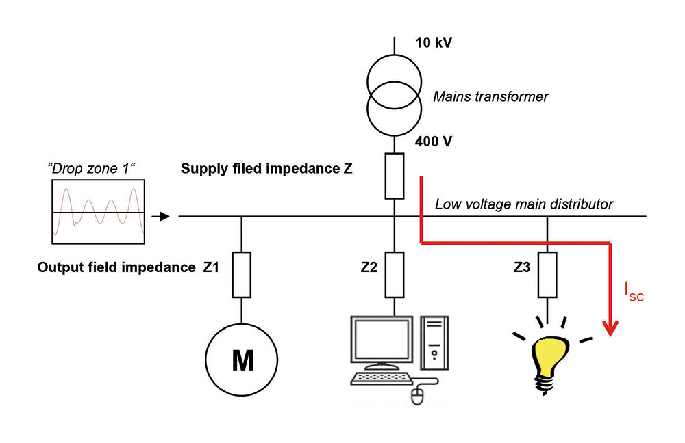
A very high current flows in the event of a short circuit in the low voltage network. The peak of the short circuit current depends on the value of the impedances Z and Z3. In practice impedance Z3 is the larger and dominating one. The value of impedance Z3 is determined by the type (cross section, material) and length of the cable amongst other things. The greater the length of the cable, the smaller the short circuit current due to a higher impedance. The short circuit current causes a voltage drop across impedance Z, whereby the voltage at the low voltage main distribution bus bar collapses briefly (drop zone 1).
In the event of a short circuit the breaker in group 3 should be tripped. If it takes more than 100 ms for the breaker to trip then the voltage drops deeply throughout the whole system for 100 ms.
3. Short circuits in the medium voltage network
Most often voltage drops are caused in the medium voltage network. Typical root causes are as follows:
- Road works
- Digging and earthworks
- Flashover in a connection coupling
- Cable ageing
- Short circuit in the overhead transmission lines (storm damage, animals, etc.)
- Lightning strikes
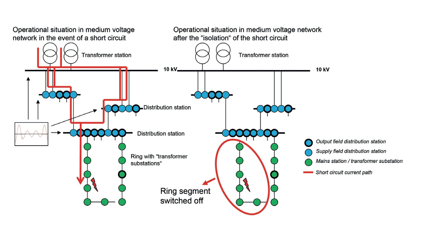
The following diagram shows a typical example for the design of a medium voltage network. The transformer substations / local secondary substations (green dots) are linked to one another in a ring and connected to a distribution main substation (blue dots). The ring is open at some point (see lower right side of the green dot ring). If there is a short circuit a short circuit current will flow (red line). This will flow until the breaker in the distribution main substation switches the ring off. This can be seen in the left diagram (in the top left ring).
Thus during the short circuit there will be a high current flowing briefly. Due to the network impedance this results in a short-term lowering of the voltage throughout the whole network. This short-term lowering of the voltage is noticeable as a "voltage drop".
Around 75% of all voltage drops occur in the medium voltage network. Often these cannot be avoided by the consumer.
Short circuits in the high voltage network
Short circuits in the high voltage network are not so common but in case they happen they are often caused by storms or (faulty) switchgear. The latter primarily in the areas at the end of a high voltage line.
Problems caused by voltage drops
Voltage drops can lead to the failure of computer systems, PLC systems, relays and frequency converters. With critical processes just a single voltage drop can result in high costs, continuous processes are particularly impacted by this. Examples of this are injection moulding processes, extrusion processes, cable and semiconductor factories, printing processes or the preparation of foodstuffs such as milk, beer or refreshments.
The costs for a voltage drop are comprised of:
- Loss of profits due to production stoppage
- Costs for catching up with lost production
- Costs for delayed delivery of products
- Costs for raw materials wastage
- Costs for damage to machinery, equipment and moulds
- Maintenance and personnel costs
The average costs of a single voltage drop vary greatly from one sector to another:
- Fine chemicals € 190,000
- Microprocessors € 100,000
- Metal processing € 35,000
- Textiles € 20,000
- Foodstuffs € 18,000
Sometimes processes run in unmanned areas in which voltage drops are not immediately noticed. In this case an injection moulding machine, for example, could come to a complete standstill unnoticed. If this is discovered later there will already be a large amount of damage. The customer receives the products too late and the plastic in the machine has hardened off. With publishers or in the paper industry paper can tear or even cause a fire. http://www.rtvoost.nl/nieuws/default.aspx?nid=119051
Susceptibility of IT systems to voltage drops and voltage interruptions
IT systems are particularly susceptible to voltage drops and voltage interruptions. This means that all processes that are controlled by microprocessors are vulnerable to this type of interference, for example
- PLC systems
- Frequency converters
- Machine controllers
- Servers at data centres
- PCs
- etc.
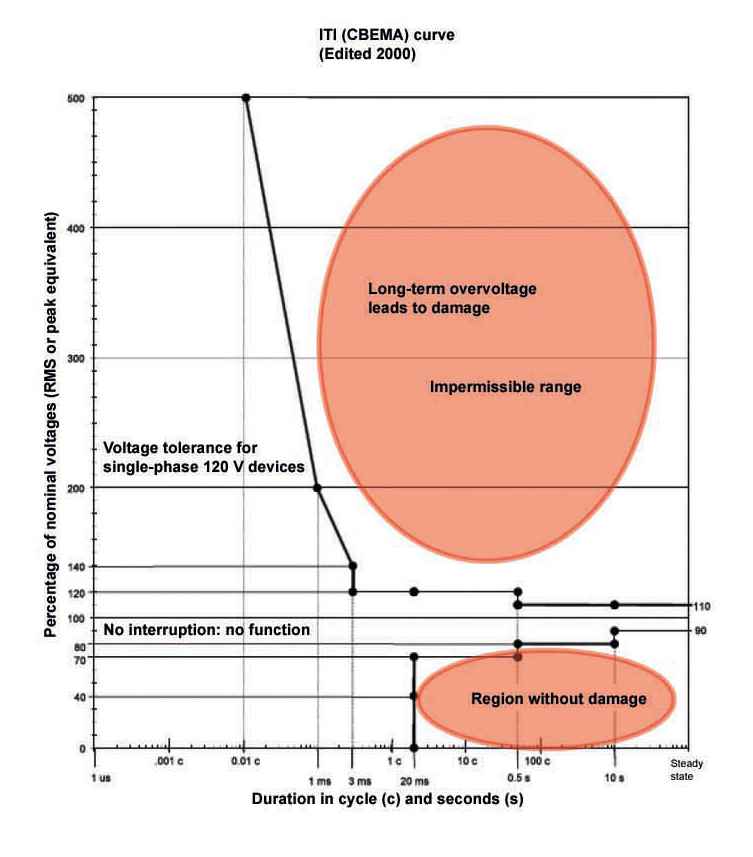
The ITI-CBEMA curve created by the Information Technology Industry Council defines when a voltage drop will lead to the failure of IT devices and when a voltage spike will result in damage to IT devices. Although the model was developed for 120‑V‑60‑Hz‑networks, it can also be applied to devices that are connected to 230‑V‑50‑Hz‑networks. The model can be used by manufacturers as a design guideline.
How can one combat voltage drops?
In some situations voltage drops caused by start-up currents can be avoided through a better design of the technical system. Voltage drops caused by short circuits in the low voltage network are generally quite rare. Most voltage drops are caused by short circuits in the medium voltage network. There is nothing that can be done to counter the causes of these drops.
The drops themselves can be prevented with:
- Static UPS, a DC power source with a downstream inverter. This solution is often employed as a bridge to an emergency power generator.
- Continuous UPS, flywheel running with the load (dynamic UPS). The energy is drawn from the flywheel in the event of a short interruption or voltage drop. This solution is not cheap and is often employed in data centres.
- Connection of control and regulation systems for a process to a stabilised power supply.
- Rework of the electrical infrastructure. This is not always possible and is certainly not cheap.
From this we can conclude that the rectification of voltage drops is no cheap business. It can be very effective to detect voltage drops at an early stage. With good reporting tools the root causes can be identified and thus enabling targeted (and more cost-effective) measures to be implemented.
Signalling voltage drops
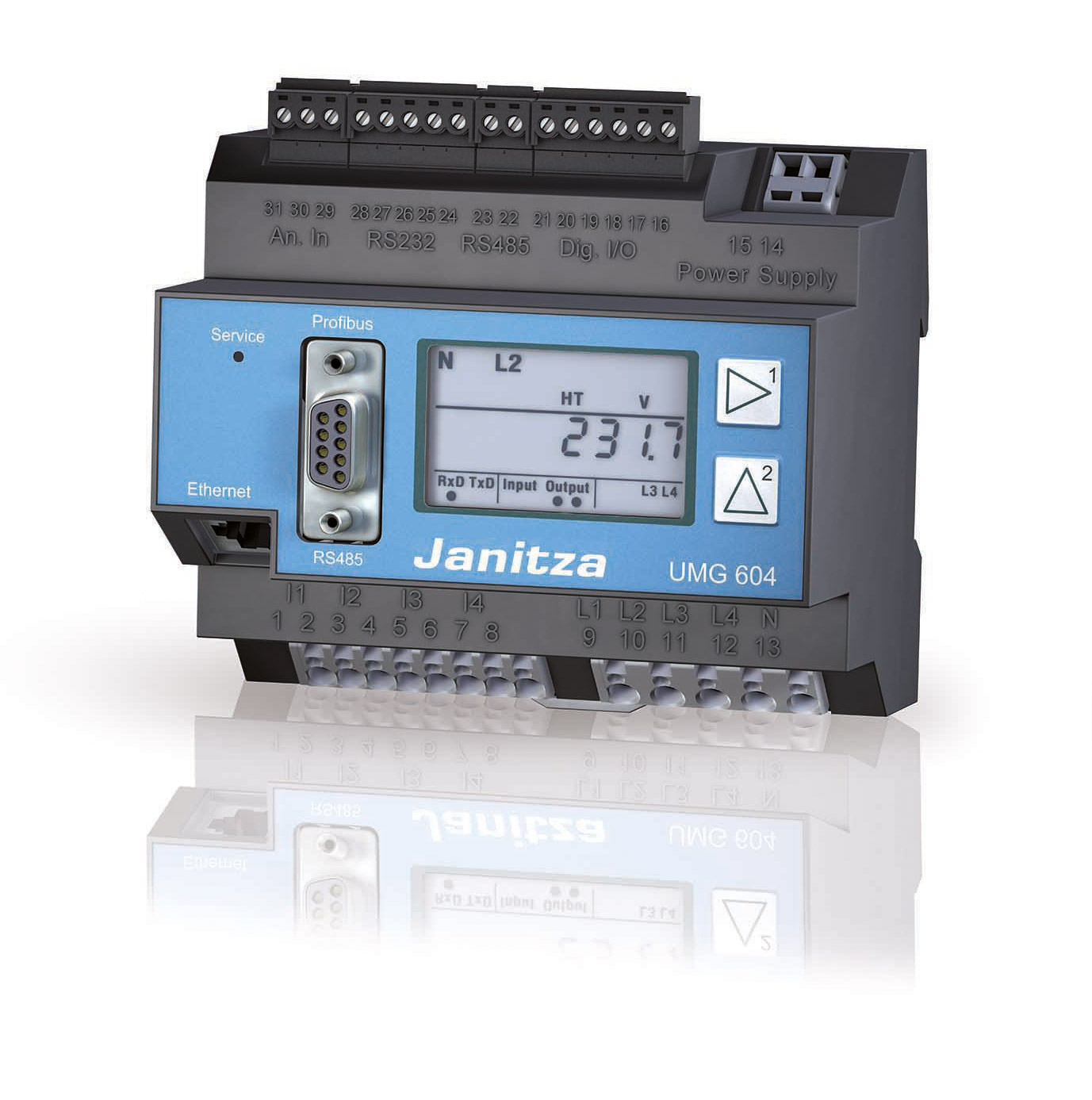
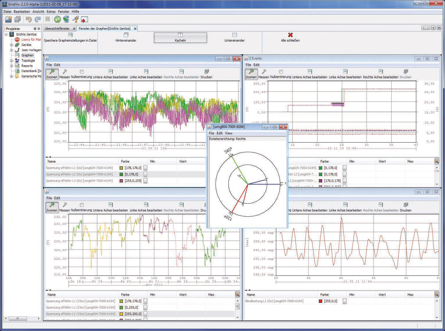
Janitza offers a wide range of analysers that are able to identify short term interruptions and voltage drops. The UMG 604 network analyser continuously monitors more than 800 electrical parameters. All channels are sampled 20,000 times each second and this enables short term voltage interruptions and drops to be signalled and recorded. An email or an SMS can be sent on the basis of these events. A comprehensive report can be generated with the GridVis-Basic software package included.
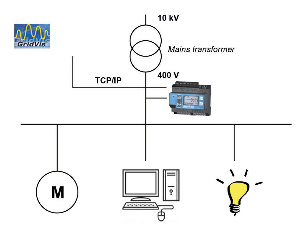
By arranging the UMG 604 in the supply field one has a comprehensive and cost-effective solution for identifying, recording, alerting and reporting voltage drops. The measurement device is equipped with a WEB-browser that offers the facility to call up the most important parameters directly from the measurement device without great investment and without complex software programs. The interruptions and voltage drops can be analysed and compiled into reports with the integrated Event-Browser.
The Janitza measurement devices for identifying short-term interruptions are:
- UMG 604, a compact network analyser for DIN top-hat rail mounting
- UMG 509, a network analyser with intuitive interactive colour screen for panel mounting
- UMG 605, a class S network quality analyser for DIN top-hat rail mounting
- UMG 512, a class A network quality analyser with colour screen for panel mounting
Analysing with GridVis Software
The GridVis basic license (GridVis-Basic) is provided along with the Janitza measurement devices free-of-charge. Amongst other things the following are possible with this software package:
- Reading out real-time measurement values
- Retrieving historical measurement data in files and graphics
- Analysing short-term interruptions, transients and voltage drops
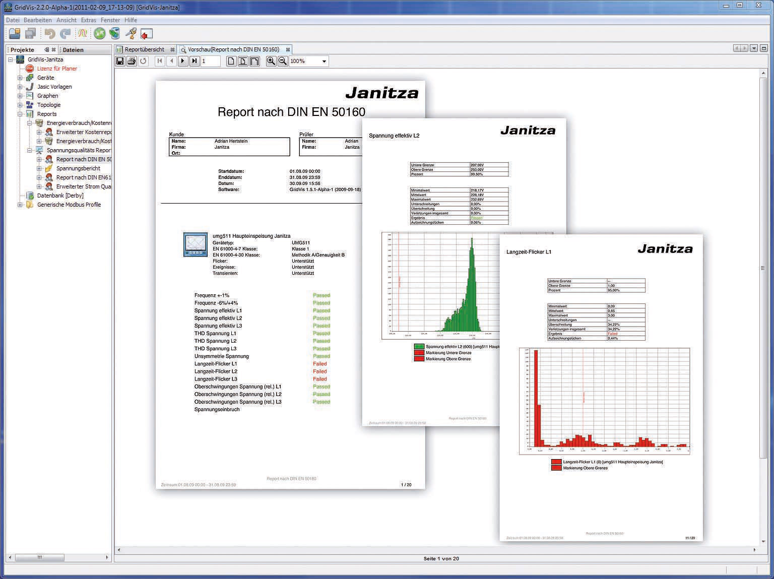
- Printing out complete EN 50160 reports at the push of a button
- Generating good/fault reports.
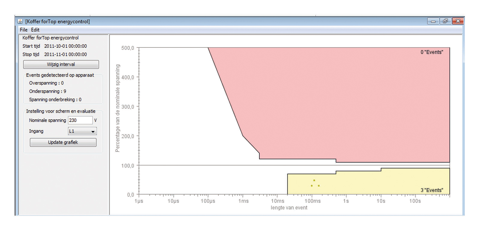
With the integrated report generator it is possible to compile concise reports yourself periodically providing an overview of voltage drops, short term interruptions and voltage spikes that have occurred by means of the ITI‑curve (CBEMA).s
In the diagram below it is possible to see that three voltage drops occurred, resulting in a system failure.
Summary
Voltage drops arise relatively frequently and are not always identified. The commercial damage caused by voltage drops is larger than that caused by interruptions. A range of voltage drops can be reduced by reworking the electrical infrastructure. The application of uninterruptible power supplies or inductors can reduce the consequences of voltage drops. In some cases however these measures are too expensive. The first step however is always the identification and documentation of voltage drops. Janitza offers complete solutions that continuously monitor and analyse complete operating processes sustainably and securely. With the application of modern measurement technology problems with the power quality can be identified and prevented in good time. An increase in supply security is guaranteed, maintenance costs will be reduced and the service life of the manufacturing plant is extended.
Sources
VOLTAGE SAGS AN EXPLANATION
CAUSES, EFFECTS AND CORRECTION
Ian K.P. Ross, MIEE
POWER QUALITY, OVER SPANNING
STROOM EN HUN INTERACTIE
Dr.ir. J.F.G. Cobben & Ir. J.N. Luttjehuizen